


Price: 31.00 USD
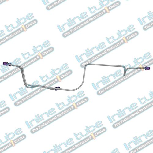
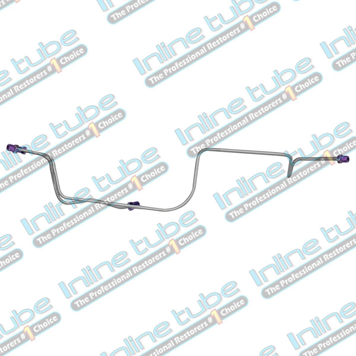
1978-1988 G-body Power Disc Rear Disc Conversion Axle Brake Line Kit OEM Steel
Axle lines
These lines typically run from the axle hose out to each rear wheel that may be disc or drum. Axle lines are usually 2 piece and feed the rear brakes. They may go straight into the rear wheel cylinder or caliper or may have a rubber brake hose that connect the rear caliper to the metal hard line so when it is time to change the pads the caliper can be removed with out having to disconnect and rebleed the brakes. In many cases axle lines have spring on them to protect the line from road debris. It is added protection to the line. Jeeps and trucks always have the spring and sports cars typically don’t.
All Lines are Preformed specify for your car or truck
Your lines will come completely preformed with correct factory bends, fittings on the ends with the correct 45 deg. double flare, or metric bubble flare ends. These lines may also have wire spring wrap, cloth wrap where on the original line. All you must do, is bolt into place.
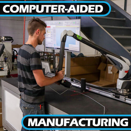
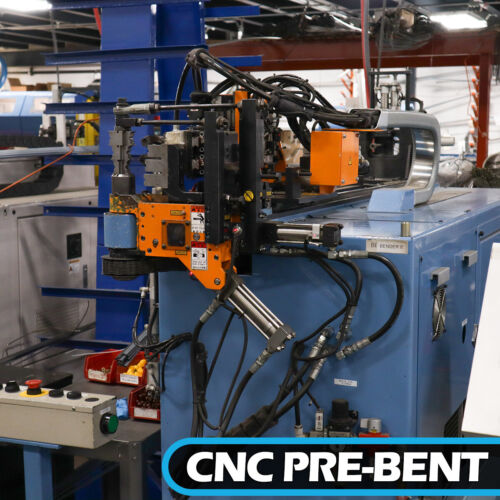
These lines are all CNC Computer Manufactured in our state-of-the-art facility in Shelby twp. Michigan USA. Our exclusive laser scans original lines or imports data from 3d models or blueprints and this information is down loaded to one of our 18 CNC benders to produce your lines. All flares and end forming are done on hydraulic end formers and pressure inspected for a perfect flare every time.
When it comes down to it not all parts are made the same, Inline Tube has spent countless hours to ensure that our product is 100% authentic in appearance, application and fit.
The difference in our product is a perfect fit.
Line Install Instructions:
Step 1. Carefully Remove Old Lines. Even with our extensive research & development we still find some cars with parts that differ from our patterns. Multiple vendors made lines for the OEM, they start and end in the same location, but the bends may be slightly different. Always remove your old lines carefully for comparison. Once you’re satisfied that the new lines match your originals, you can dispose of the old lines. If your old line is different, we may need a picture or your original line as an example of what is right for your car.
Step 2. Before Altering A Line. Make sure the line you are comparing to is an original line. If your line has a long fitting on one end and short fitting on the other it is remade. If the line has wave like bends and wraps around to take up the slack in the line it is remade. The original line will have crisp clean bends just like the replacement line. If a line must be altered to fit a non-stock application, (line lock, dual master, disc brake conversion) or your application varies from our part beware, once the part is bent up, cut, and not in the original shape it is not returnable.
Step 3. Clean and Prep Junction Blocks. In most cases you will be re-using the cars original brake distribution block, proportioning valve, or other blocks that are not available new. These blocks should be cleaned and inspected before reassembly. Inspect the cone shaped seat in the bottom of each port. If the seats have multiple crush rings or off-center crush rings you may have trouble with leakage. If the seats look bad you may consider finding a replacement part from a junk yard or parts car. In some cases, blocks are available new.
Step 4. Routing the new Lines. Route the new lines into place of the old lines on the car. The end caps protect the threads. Carefully route lines in existing clamps and start the line bolts in the clamps.
Step 5. Start Threading. With the new lines loosely in place, be sure the ends are near the port where they will install and pointing the proper direction. Leave all connection points such as valves, blocks, clamps, and wheel cylinders as loose as possible, this will give you some free play while you are starting the fittings. Your new lines should line up close to the attaching points. You may have to align the new lines slightly by gently bending the ends into place. It is crucial that the lines are straight into the hole. The flair and the seat must be aligned for a leak proof seal. Remove the end caps and finger tighten all fittings. Do not tighten any fittings clamps or blocks until all lines are in place.
Step 6. Finishing the Job. With all fittings started, tighten all blocks and clamps. Now fully tighten all fittings. When tighten fittings make sure to use a line wrench. Your new lines are now installed. Fill your master cylinder with new brake fluid. Bleed the air out of the entire system. Once the system is bled, check each connection for leaks.
Lines that still leak. If you have a leaky line on a new component the line has not been tightened enough to crush and seal the line to the brass seat or it is not aligned to seal against the seat. Untighten the line re align as needed and retighten to force a seat between the brass and the line flair. The cone should have a ring crushed into it all the way around. We refer to this as a witness ring. If the ring does not go all the way around the line is not centered. We recommend Placing a deep socket the size of the fitting hex over the end to slightly bend the line. Repeat until a seat ring occurs which will stop the leak. With the flare on the cone, slide the tube nut up and tighten finger tight. Use a Line wrench to tighten the nut � of a turn. Then loosen the tube nut and repeat this process. Each time tightening with the wrench a � turn more. The tube nut should go a little farther with your fingers each time. Repeat this process 4 times loosening and tightening. After the 4th time of finger tightening snug the flare to the cone with your line wrench. You have now created a perfectly centered flare seat and the line should not leak. If you have a leaky line on a used component or block see step 2. Align to old crushed seat or get a new component.
Never use Teflon to seal lines. Teflon seals the threads to the component but does not stop the leak. Remember the cone of the component and the flare of the tube is what seals the connection. The tube nut only holds the flair to the seat. Teflon is only used on pipe fittings (tapered fittings) not on brake line fittings.
Stainless VS Steel Lines. Steel lines are a carbon steel that has a copper coating on the inside of the line and a silver zinc finish on the outside to prevent rust. Our steel coated lines will last as long as the originals did. Stainless steel lines are a premium grade aircraft 304 stainless. They are fully annealed and as soft as they can be. We order our tube direct from the mill to our spec so that you can bend and flair this material. It is harder than the mild steel but very workable and will seat just fine.
Consult Your Mechanic. This is intended for use as a basic guide to help install new brake and fuel lines. If you are unsure about any part of the installation procedure, please consult a professional mechanic for assistance. Inline tube assumes no responsibility for improperly installed lines.
Choosing a FLUID. Standard DOT 3 brake fluid is in all new car braking systems, if you intend to use DOT 3 fluid, be sure it has not been exposed to moisture. An open container of DOT 3 fluid will collect moisture from the atmosphere. DOT 3 fluid will also destroy your paint, so do not spill on paint.
If you are going to use DOT 5 (silicone fluid) it repels moisture and will not harm your paint. Under extreme braking conditions (Constant drag racing) or excessive braking DOT 5 does not perform as well as DOT 3. When DOT 5 fluid heats up, performance decreases.
When changing a system over to DOT 5 be sure to flush out all reused components, blocks, cylinders, and lines. DOT 5 & DOT 3 Fluids should never be mixed.
Shipping Bends
Shipping bends are required on all lines over 6′ in length. Unbend between the white tags. The bend will roll out by following these few steps. Large bends do not stress the tube so the tube will become completely straight. Position the tube on the floor keeping the bend perpendicular while using the floor as a straight edge. Roll the tube against the floor working out most of the bend. After most of the bend is straightened, using you knee the remaining bow can be removed. The remaining minor waves are removed by hand straightening.
Item specifics
-
Condition
-
-
Brand
-
Inline Tube
-
Manufacturer Part Number
-
CMB78RC1
-
Placement on Vehicle
-
Front, Left, Lower, Rear, Right, Upper
-
Country/Region of Manufacture
-
United States