1978 Cutlass

Steven94

Not-quite-so-new-guy
Mar 3, 2024
10
0
1
New to the forum! I have a 78 cutlass and I’m trying to figure out all the wiring if someone could help me out.

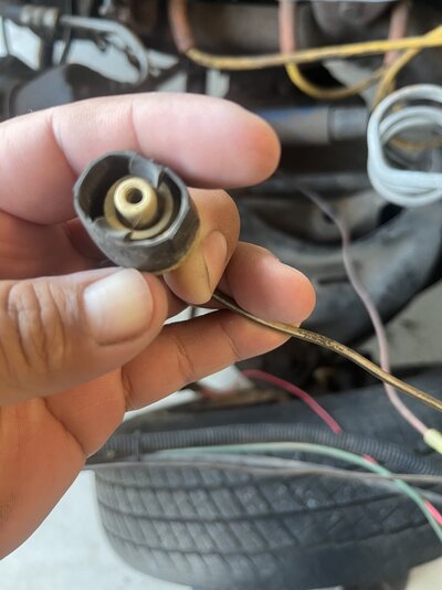
1st pic brown w/white strip no sure where it goes

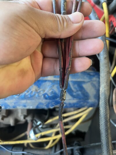
2nd pic red coming from firewall spliced into 4? Is this original?

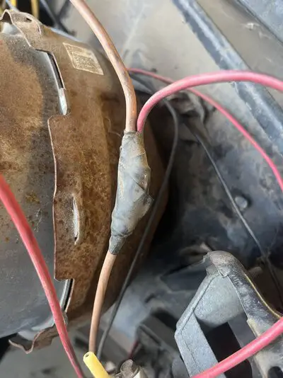
3rd pic tan from fire wall spiced not sure were red end goes. Tan went to distributor

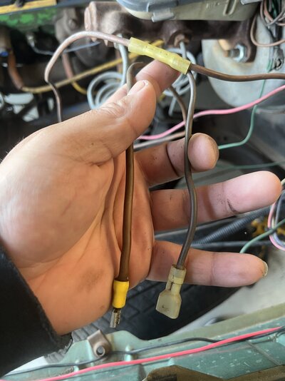
Last pic brown from firewall spliced not sure were either end goes
 

Attachments

  • IMG_1017.jpeg
    IMG_1017.jpeg
    1.5 MB · Views: 24
  • IMG_1018.jpeg
    IMG_1018.jpeg
    1.5 MB · Views: 23
  • IMG_1020.jpeg
    IMG_1020.jpeg
    1.8 MB · Views: 20
  • IMG_1022.jpeg
    IMG_1022.jpeg
    1.5 MB · Views: 24

ELCAM

Royal Smart Person
Jun 19, 2021
1,124
1,270
113
1- Brake warning light, goes to the proportioning valve.

2- Factory splice in the number 2 circuit, fuseable link to starter, spliced to HVAC blower motor relay, alternator and the C100 bulkhead connector.

3 and 4 have been modified would need more information to figure out what someone has done.
 
  • Like
Reactions: 3 users

Steven94

Not-quite-so-new-guy
Mar 3, 2024
10
0
1
1- Brake warning light, goes to the proportioning valve.

2- Factory splice in the number 2 circuit, fuseable link to starter, spliced to HVAC blower motor relay, alternator and the C100 bulkhead connector.

3 and 4 have been modified would need more information to figure out what someone has done.
What info might help you help me?
 

ELCAM

Royal Smart Person
Jun 19, 2021
1,124
1,270
113
Where the wires go would be helpful or pics of all of the wiring in question.

Picture 3 is likely the other number 2 circuit and it is supposed to be a fuseable link that goes straight to the C 100 bulkhead connector. Looks like someone spliced something else into it.

FYI - Factory splices look like pic number 2 crimped and soldered. So if you untape pic number 3 and it doesn't look like the splice in pic number 2 it is a modification.
 
  • Like
Reactions: 1 users

Steven94

Not-quite-so-new-guy
Mar 3, 2024
10
0
1
Where the wires go would be helpful or pics of all of the wiring in question.

Picture 3 is likely the other number 2 circuit and it is supposed to be a fuseable link that goes straight to the C 100 bulkhead connector. Looks like someone spliced something else into it.

FYI - Factory splices look like pic number 2 crimped and soldered. So if you untape pic number 3 and it doesn't look like the splice in pic number 2 it is a modification.

Not factory
image.jpg
 

Steven94

Not-quite-so-new-guy
Mar 3, 2024
10
0
1
Original wire goes to the firewall
image.jpg


One end goes to the distributor (Tan original gauge wire) and the red end is cut off no connector.
 

ELCAM

Royal Smart Person
Jun 19, 2021
1,124
1,270
113
Pic 3 also might be circuit 3 pink for HEI +12V.
 
  • Like
Reactions: 1 user

ELCAM

Royal Smart Person
Jun 19, 2021
1,124
1,270
113
Looking at the picture you just posted the number 3 from the original post does look like the HEI pink wire that has been painted.

Which of the boxes does it connect to on the S100 connector? Sorry crappy picture.
S100 engine harness.png
 
  • Like
Reactions: 1 user

GBodyForum is a participant in the Amazon Services LLC Associates Program, an affiliate advertising program designed to provide a means for sites to earn advertising fees by advertising and linking to amazon.com. Amazon, the Amazon logo, AmazonSupply, and the AmazonSupply logo are trademarks of Amazon.com, Inc. or its affiliates.

Please support GBodyForum Sponsors

Classic Truck Consoles Dixie Restoration Depot UMI Performance

Contact [email protected] for info on becoming a sponsor