Thought I had some pictures of the conversion job from auto to manual that I did for my own Monte but apparently I never did generate a complete set of pics
This is what I elected to do to brace the one arm on the Z-Bar. The actual brace is 1/8th x either 3/4 or 1 inch angle that I cut and shaped to match the od of the tube and the angle at which it butted up against the arm. Mig welded it all together and did some finishing to it for the pretty factor. The other end is done about the same way.
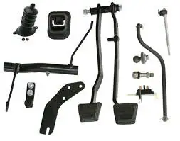
All my parts for this exercise were factory items that i had harvested from various hulks over a number of years. What that did was to give me an already assembled swing pedal set, several in fact, from which i could chose the best pieces and build what I wanted.
For my Monte, the holes in the frame for the bracket actually were already there, just covered over with a lot of paint and assorted crud. Cleaned them out and used a set of factory bolts for the install.
As pointed, the hole on the block ought to be there and tapped. Physically it is located just above the mount for the oil filter. Take a chasing tap and run it into the boss to clean it out before trying to run in the pivot ball. If the Z bar that you get comes to you with a plastic plug popped into a hole in the tube, pull the plug and install a grease fitting. That is the why of that hole and makes keeping the Z lubricated a whole lot easier that taking it apart to do it.
Don't see the two springs in the picture. You will need a clutch return spring and there is also one that rides along side the rod between the Z-bar and the throw out arm to keep the rod from popping out once it is adjusted. i can upload a picture of that if you think it might be useful.
Just a couple of shots of the Z-Bar post modfication, showing the the bracing for each end. plus a some shots of the assembly as it is attached to the frame. You may have to tweak the path that your front brake line to the driver's side caliper uses or the Z and the line can seriiously rub on one another.
A note about Pic #4, The arm showing in that picture is the lower arm to which the rod for the throwout arm would be mounted. To get the alignment between the rod and the arms that i wanted, I had to both twist and bend the outer ear of that arm and what you see is the offset that I had to create to make me happy. For the welding aspect, I Vee-d both sides of the plate for each end of the joint and did the welds. They were deliberately left proud of the original surface to leave as much material as possible in the interest of strength. Did not see any point in pretty as you never see it most of the time and anyone wanting a closer look is going to have to imitate an earth worm to do it.
Nick


.JPG")


