Sounds like possible bad sensor in the OP Sensor. Easiest method is compare against another one. Then when it's wired correctly and engine running ... How does it read? Does it start at 60 psi and then go down to 35 or so, but goes up and down with rpm change? Or does it go to 60 and regardless of rpm, just stay there?
If you apply 12+ to the gauge and ground it, the needle should swing high IIRC. When you apply 12+ to the gauge and connect it to a correctly working sensor/sender and it is grounded through the block, resistance is high and needle is low. Start the engine and resistance decreases and needle swings higher. Raise RPM oil pressure go up, resistance in sender again decreases and needle swings higher. At least that's the theory. Could be other way around but if I remember correct, resistance down as pressure goes up.
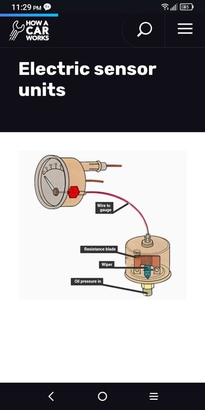
The gauge is actually closer aligned to an amp gauge that reads more or less by current going through the gauge. The OP Sensor/Sender functions more like a rheostat adjusting current through it by altering its electrical resistance based off of the oil pressure.
Fans are on separate circuit. You have the temp sender and the controller which should be adjustable to turn fans on at a specific temp and shuts fans off at a specific temp. These are usually powered via a 30 amp relay. I usually wire each fan to its own 30 amp relay.
The temp gauge works similar to the OP gauge and needle moves based on current moving through it. This is based off of how much (or little) current flows through the Temp Sender mounted in the water jacket (hot coolant) typically forward area of the intake manifold where the hot coolant leaves the engine and flows into the radiator.
Fuel gauge is similar. As the float moves up and down the resistance changes and like above..., the needle changes. Tank is full, float is high and specific calibrated resistance moves needle to full. Opposite is true, tank empty, float is down and needle responds to that current that has been adjusted due to the change in resistance, needle goes down.
If you put full 12+ (13.7 or so) on the gauge and then full ground, the full current available is going through the gauge and would account for gauge immediately reading high. You have to be careful not to burn it up when doing this. Always remember a current (Amp) gauge is always mounted in series with the load and a volt gauge is always mounted in parallel or they won't work.