The way I've made the covers in the past is to take a stock metal faceplate and cut off the face leaving about an 1/8" flange around the edge.
Then I make a new faceplate out of sheet metal that I drill my new holes in and you can either pop rivet it to the original faceplate or tack weld it.
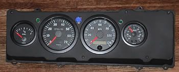
This was the first faceplate I had done back almost 10 years ago:
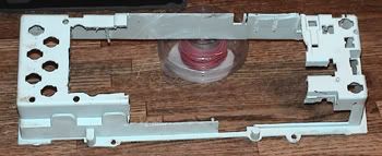
And what you have to do with the stock "bucket" piece in back:
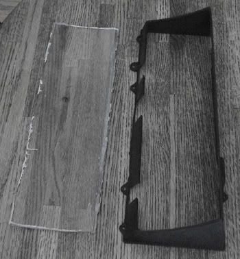
I also trim the stock clear plastic cover to remove the face and then paint it black. Keeping this in place finishes off the sides of the gauge panel so that you can't see behind the dash:
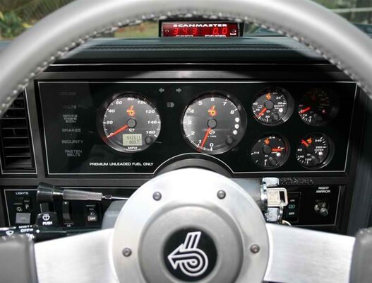
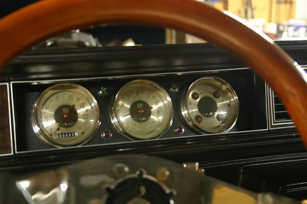
My latest setup is this:
I like the quad gauge on the far right since it incorporates the oil, water, fuel and volts into one gauge. Much easier to fit, although it is admittedly a bit harder to read. They look more like stock gauges in that you basically have a low, medium and high point tick. Which is fine for me since if I really need to monitor the vitals of the engine I can plug the laptop in and get direct readings.
In my first design above I used LED signals from Painless Wiring and they worked great. However I will warn you that they are very bright. Not a huge deal with the turn signals but that blue LED for the high beams could blind you at night. It really could have used some sort of a resistor or something wired into it to cut the light output.
On my second design I wanted some LED's that looked a little coolers and found the ones pictured at an electrical supply house online. To dress them up a bit I bought some chrome plated washers at the hardware store that I put under them before bolting them down. Gives a little more dimension to them.
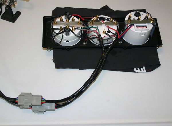
Something else that I did on my second design was make the cluster easier to remove. The first time around I just used some 1/4" insulated male and female spade connectors for each connection. But they are really hard to pull apart.
This time around I used a couple of Deutsch connectors and made the wiring harness long enough so that I can unbolt the cluster, pull it out and then disconnect the wiring harness. This is the back of that gauge cluster:
Pretty simple to make these. I wish I had the time and resources to be able to make these and sell something similar to people but unfortunately it just takes too much time to make them. Maybe one of these days when I have my own home CNC router or laser cutter I can.
🙂