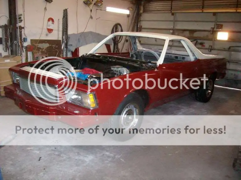
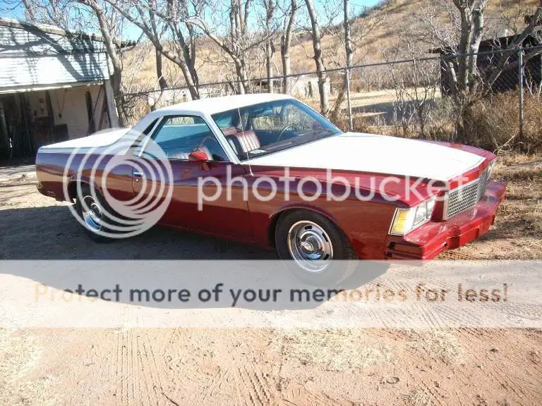
500 Cadillac in a G Body

Mike P

Master Mechanic
Aug 7, 2009
446
208
43
Arizona
I broke down my El Camino/Monte Carlo front clip/500 Caddy conversion at the request of a couple to make it a bit easier to read. The first 2 parts covered the body work portion and 9 in Ford rearend setup.


viewtopic.php?f=41&t=25429

viewtopic.php?f=14&t=25389


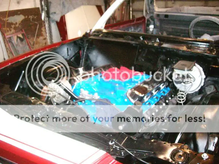
This thread will cover the 500 Cadillac/TH400 swap portion of the build. As the engine compartments of the G Bodies are virtually identical this should pretty much apply to stuffing a caddy motor into any of them. This is the way I installed the engine and transmission in my swap and is definitely not the only way to do it. There are different engine mount kits out there (or a person could build his own), different crossmembers and different ways of routing exhaust etc......this is just how it worked out for me.

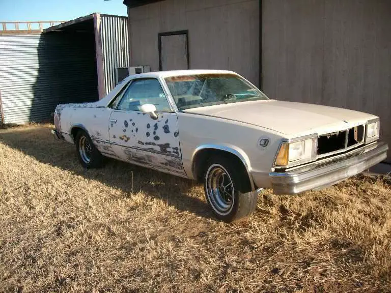
The whole project petty much came about because I had a 500 Cadillac engine I picked up years ago and was waiting around for the right project to stuff it in.......it turned out to be an 83 El Camino parts truck I ended up with.
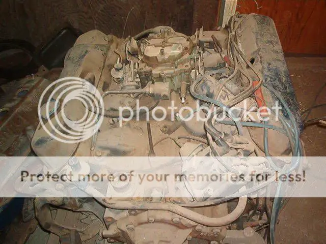
500CI.jpg


833quarter.jpg


I bought the El Camino as a parts truck and even though the guy said he had a title for it it ended up taking a couple of months to get it in my hands (and I sure wasn’t going to start a project this involved and expensive without legally owning the vehicle). While I was waiting on him, I went ahead and took care of a couple of things on the motor.

The first thing I addressed was the pulleys. The majority of the 60s/70s 472s and 500s used a system that REQUIRED a smog pump (the pump is driven by the crank pulley and it in turn drives the water pump).

68ELDOPULLEYSBELTS-1.jpg


I got lucky and scored the 1970 only non-smog pump set up.
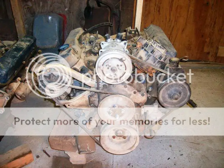
Pulliesbelts.jpg


The other option would have been to try to find a late 70’s 425 powered Cadillac which ran a similar set up but with a single AC/PS belt.


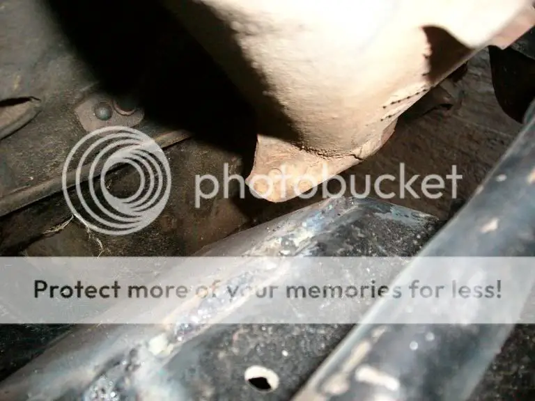
The only stock pan that will work with this swap is the rear sump El Dorado pan and as my engine came from an Eldo I had the right one. One of the potential issues with using this pan is that it is a dual sump unit with 2 drain plugs. The front sump holds about 1 Qt of oil and needs to be drained during oil changes etc. The problem when using it in a G Body is that the front plug sits right over the crossmember and depending on how low you set the engine the plug can be inaccessible or at the very least very messy to change oil.

The ridge that forms the front sump and holds the oil is for front axel clearance (the Eldos were FWD with a transaxle). I decided to eliminated the front sump holding oil by heating the ridge and then using a piece of pipe over the heated area and hammering the ridge down to provide a way for the oil to drain back to the main sump.
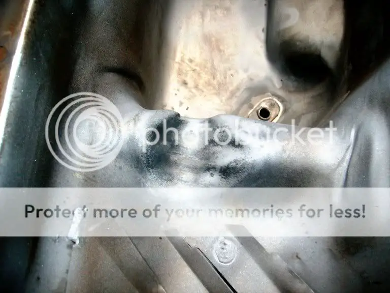
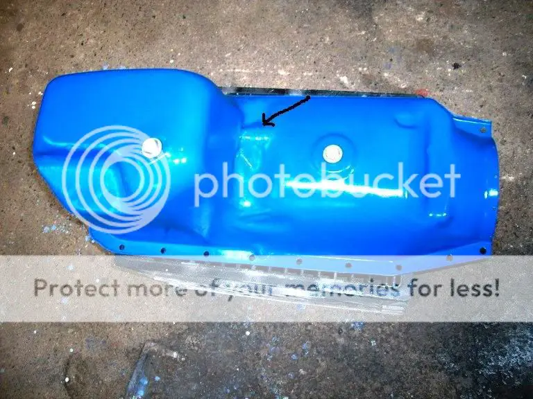
oildrainback.jpg


OilpanmodArrow.jpg


The final thing I did while waiting on the title was to convert from the old A6 AC compressor to the smaller Sanden 508 style. They do make a bracket set to do this (at about $100), but when I started checking around no one actually had one on the shelf. After studying the A6 bracket for a while, I figured out I could simply enlarge the saddle area, elongate the holes, and build a simple rear bracket to mount the Sanden. It worked great and the belts lined up perfectly.
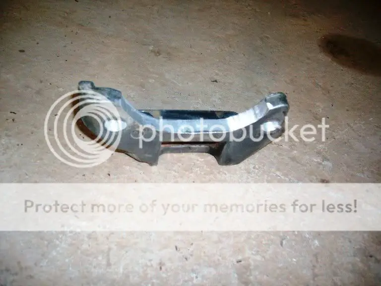
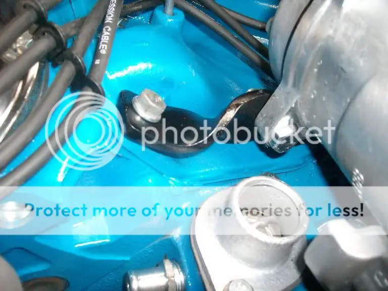
ACBracket.jpg


ACBrace.jpg
 
  • Like
Reactions: Mikej89 and DRIVEN
And then at last the title finally came in and I was able to actually get serious about the swap.

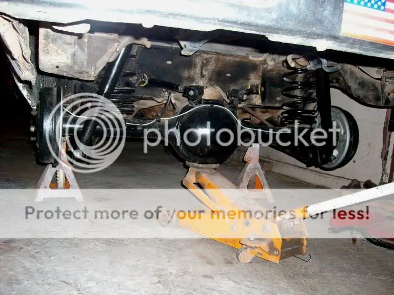
One of the first things I did was bolt in the Ford 9” I had built so I could finally stop tripping over it.

9Inchin.jpg


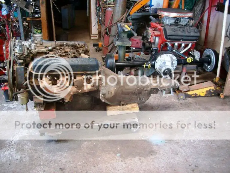
I elected to use a TH400 and a fairly high (2.75) ratio gear set for this project. There were several factors involved with this decision. An overdrive transmission (with a 3.50) gear ratio was appealing to a certain extent but in all reality chances are all it would do with street tires would be to make a lot of tire smoke in 1st gear. The major consideration against using a 700R4 or a 200 4R was simply the cost. By the time either of these transmissions are built to hold the 500+ foot pounds of torque the 500 makes they become a very expensive transmission. So in the end the old reliable TH400 was bolted to the engine.

The picture below also shows the engine with a driver’s side RWD 472 exhaust manifold that was needed for clearance in a G Body.
5001.jpg


I started out by purchasing the G Body motor mount kit from MTS which consisted of a handful of metal pieces and a pair of stock El Dorado Motor mounts (this shows the metal parts for 1 side). I only ended up using the 2 larger pieces on each side as I built my own gussets. The price was a bit over $100, but when you consider I didn’t have to hunt up the motor mounts or spend time bending and drilling 1/4” plate it was worth it to me. I have heard there are now a couple of other kits available now to include one that is bolt in but that uses solid motor mounts.

halfmountkit.jpg


The plates with 2 holes in them are what the motor mounts bolt to. The problem with that is the motor mounts are splayed (the bolts are at an angle when bolted to the engine). This means to install/remove the engine the mounts have to be unbolted from the engine while it is still in the car. To alleviate this I slotted the passenger side plate once the engine was back out after the trial fit.

slottobecut.jpg


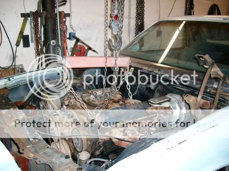
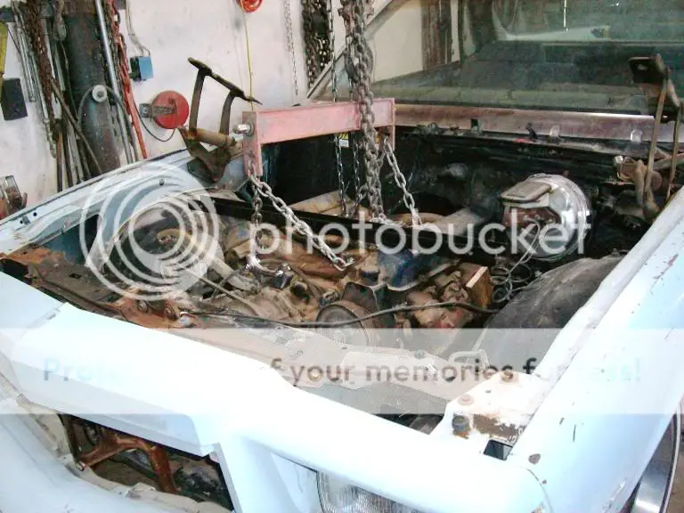
I was using an engine leveller to install the engine, and like most installation you have to use the next to the last intake bolt holes to allow enough angle to set the engine and transmission in as a unit.

Chainposition.jpg


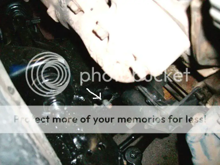
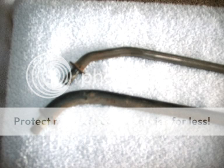
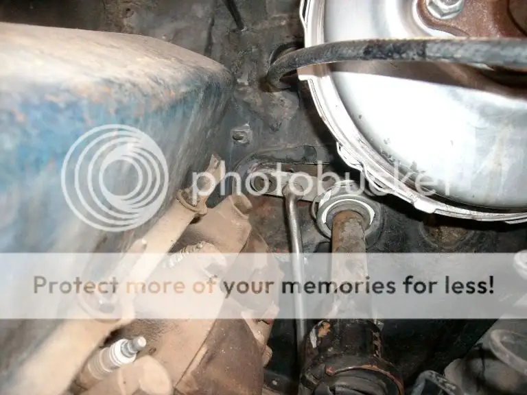
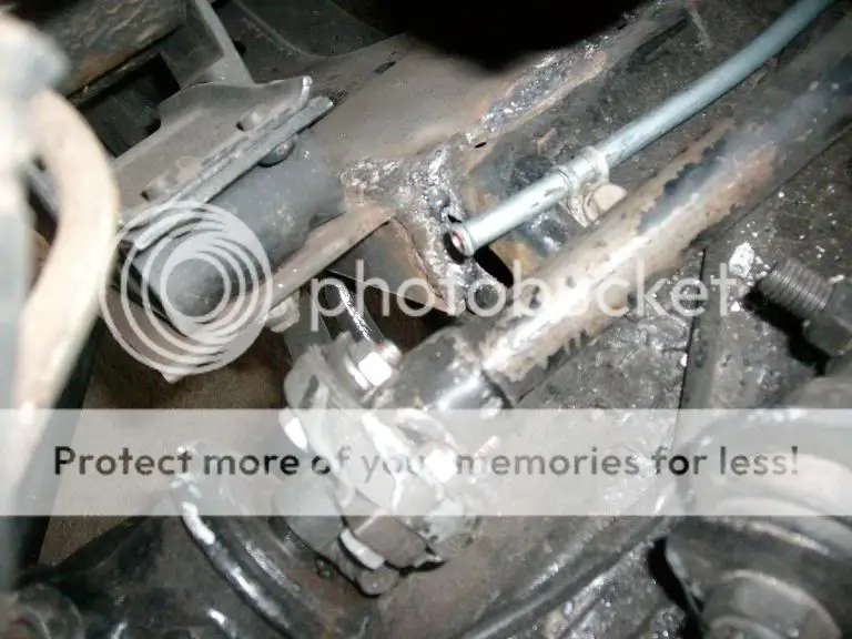
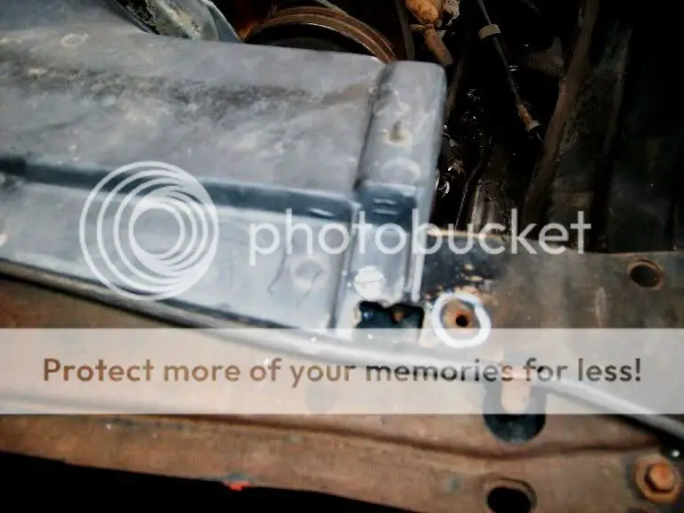
I found out when I got the engine in that there were a couple of things that interfered with the engine that should have been removed .....the column shift rod and for the ones with the fuel line on the passenger side, the fuel line where it comes thru the frame. You will also want to remove the oil filter prior to installing the engine as chances are good it will interfere with the sway bar.


shiftarmint.jpg


frameline.jpg


Although it is possible to do the install without removing the AC box (if so equipped), in many cases there will be interference with the passenger side valve cover. I would recommend you remove the box and with the engine in you can reinstall it and modify by cutting and re-fiberglassing the box to fit if necessary.
 
  • Like
Reactions: Ugly1
Then it was time for the most time consuming part of the project, installing and aligning the engine. I set the engine in with the exhaust manifolds installed as they can be a major interference area unless the engine is exactly positioned.

enginstall1.jpg


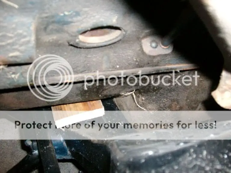
Once the engine was close, I set a 3/4” piece of wood between the front sump on the pan and the crossmember to make sure I didn’t lower the engine too far.

cribbing.jpg


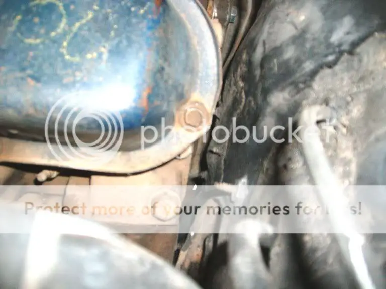
And as the engine is longer than the SBC it is replacing I moved to engine back as close to the firewall as possible without actually touching it.

firewallclearance.jpg


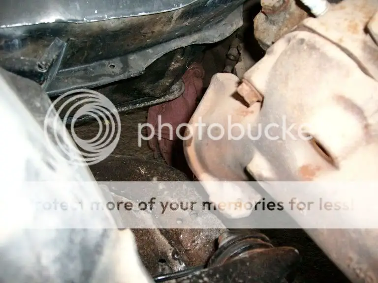
Side to side location was determined by splitting the difference between where the exhaust manifolds each had the most amount of clearance......resulting in the engine being shifted to the passenger side by about 1 1/2” from the centerline the SBC sat at.

Passexhausr.jpg


driversexhaust.jpg


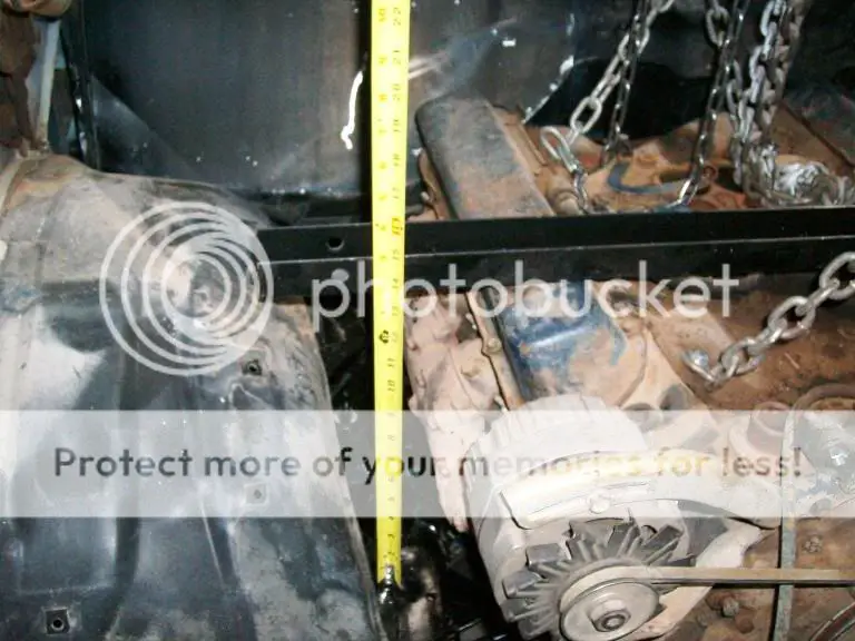
As my shop floor is not exactly level rather than use a bubble level to make sure the engine is level from side to side, I set a straight piece of metal across the valve covers and measure down to frame rails on each side.

leveling1.jpg


leveling2.jpg


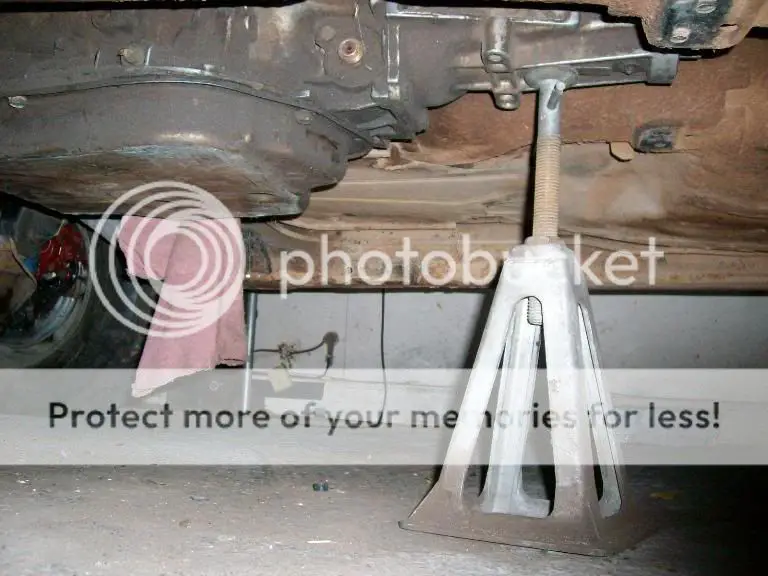
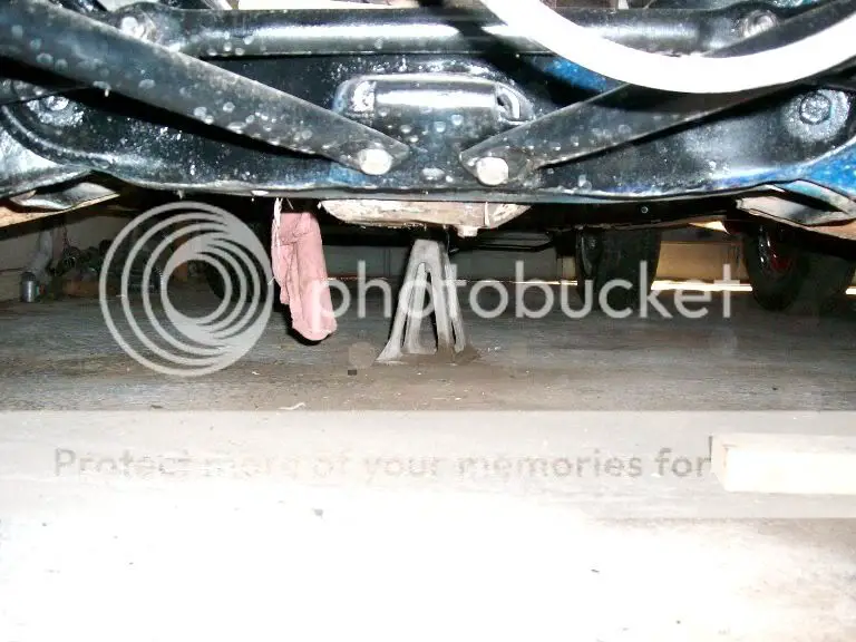
To hold the rear of the transmission up and level the engine front to rear, an old mobile home levelling jack was used.

trannyleveling.jpg


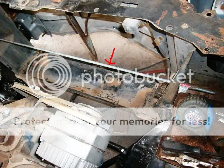
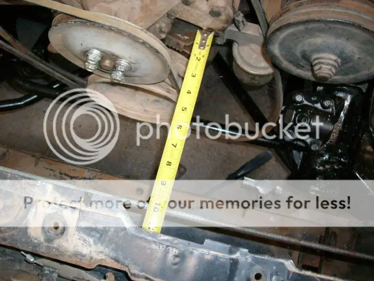
Finally to square the motor in the engine bay I ran a piece of metal thru a pair of existing holes in the radiator support and took measurements from the water pump mounting holes on both sides and adjusted until the readings were the same.

measuringbar.jpg


measuringfront.jpg


The steering was a little snug, but in a pinch it would do (and later on I made some changes that gave me a bit better clearance.

steeringclearance1.jpg


The only thing I really didn’t like was that the pan sits slightly lower than the crossmember but I decided that I could live with this as the El Camino sits a few inches above stock ride height.

oilpandepth.jpg
 
When I was finally happy with how the engine sat I bolted the mounts to the engine and attached the mounting plates to the motor mounts. Then I placed the L shaped plates on the crossmember and started tacking everything together.

Lmotormount.jpg


bracketclamped.jpg


brackettacked.jpg


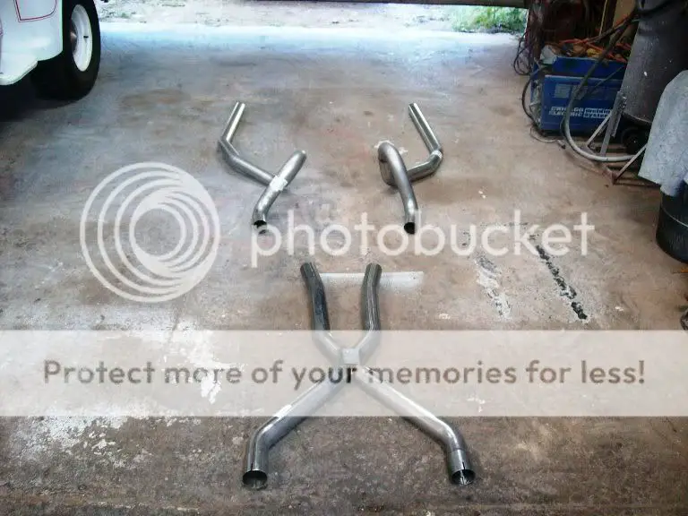
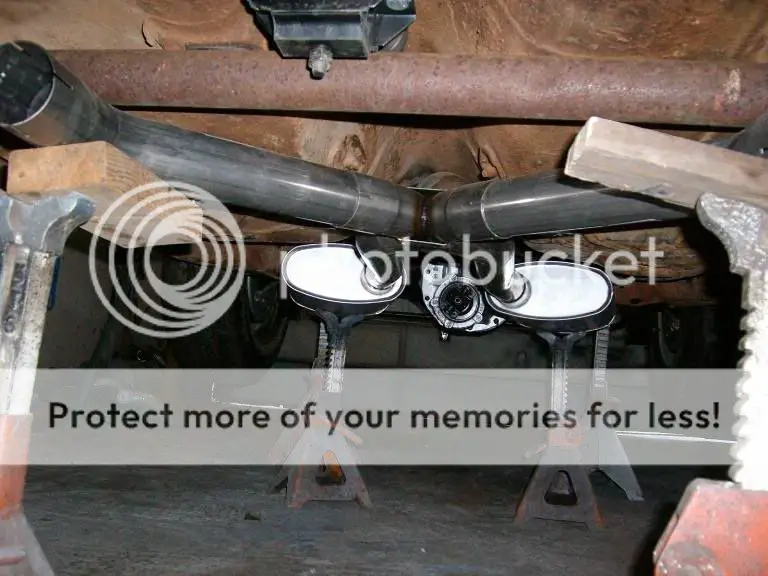
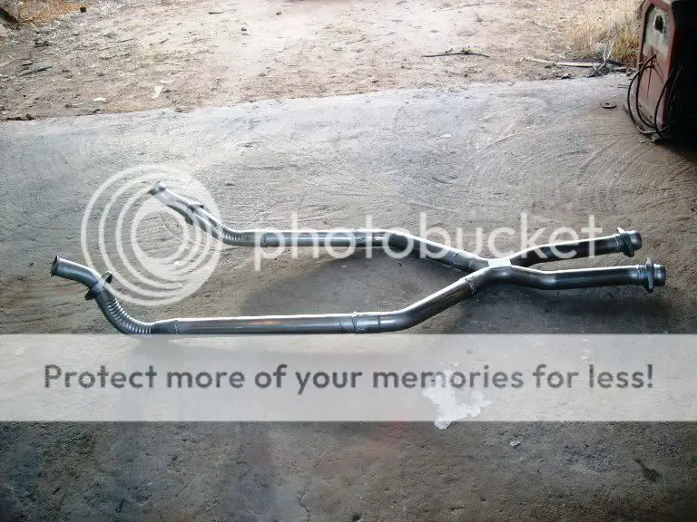
I usually leave the exhaust till last on a project, but in this case I bought most of the exhaust early on in the project because I knew I would need to figure out where it would go to make the crossmember. The majority of the system is a Pypes X pipe and Flowmaster tailpipes (2 1/2")

500exhaust.jpg


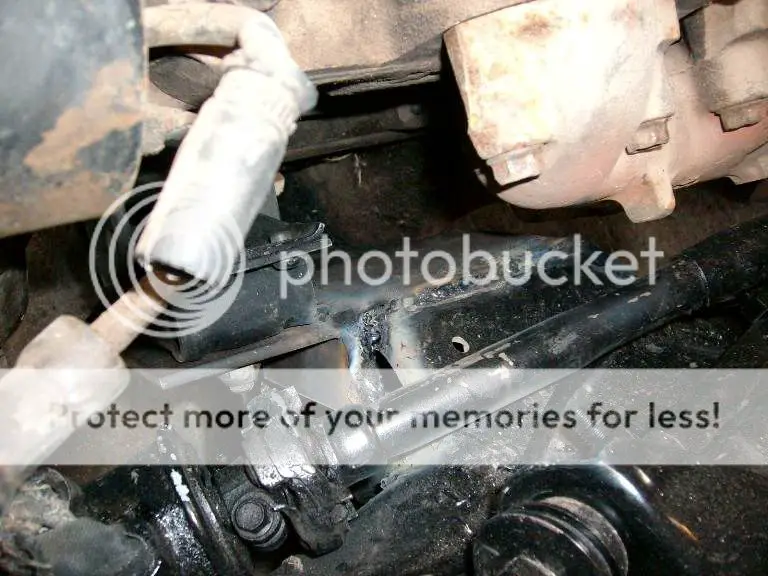
The crossmember itself was about as simple as I could make it. It is basically a piece of thick wall pipe with angle iron pieces welded to the ends so it sits up in the frame rails and the foot for the transmission mount from a donor crossmember welded to it. I determined where the reliefs for the exhaust needed to be and simply heated the area and hammered the reliefs in (not shown in this picture is a piece of 1” angle iron I welded to the back to make it a bit more rigid).

pipefitting.jpg


crossmember.jpg


With the engine and transmission finally set in place where it wouldn’t move I started on the exhaust. Plans for the 500 were to basically leave it stock and while headers would slightly improve the performance for me it wasn’t worth the hassle and cost. From what I’ve read nobody makes a set of bolt on headers that will work with this swap (even the shorty headers don’t clear the crossmember) and most people end up using a set of BB Chevy swap headers and cut the flange off and replace it with a Cadillac flange or go with a completely custom set.

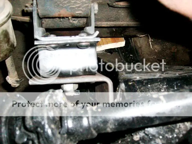
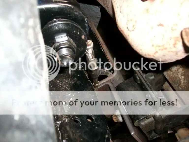
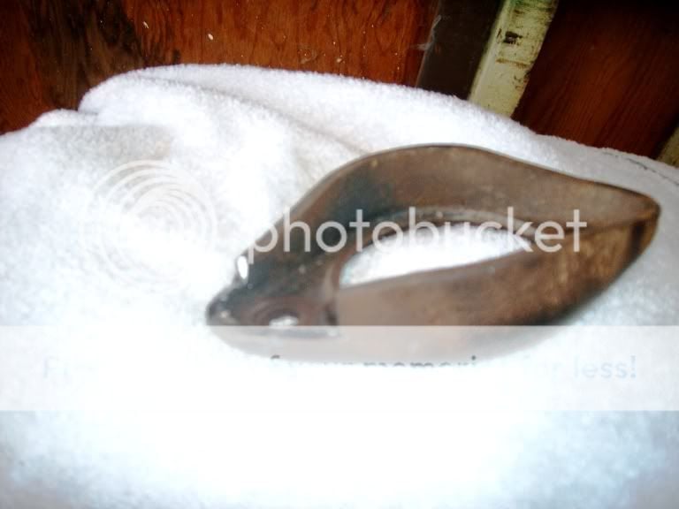
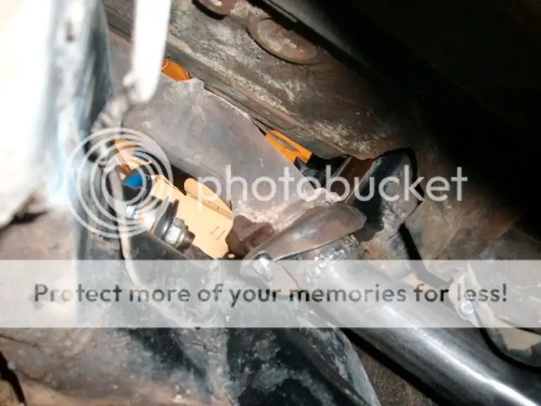
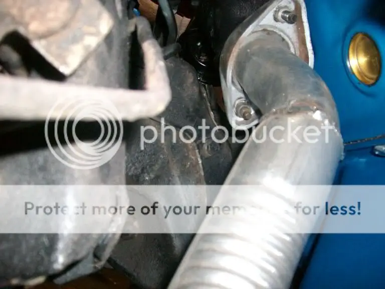
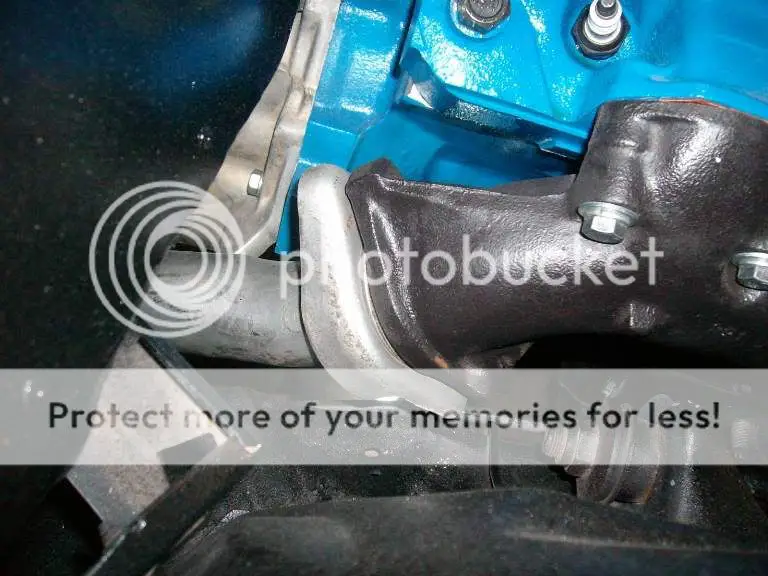
Even with the exhaust manifolds clearance is tight. The passenger side just clears the crossmember, and while the drives side has a bit more clearance when installed I had to trim the flange in order to get it past the frame rail.

driversflange3.jpg


flange.jpg


pass2.jpg


But at least when all was said and done the pipes did fit and I was able to go on with the mockup. When the engine was back out I went in and with some heat and a BFH, I added a bit more clearance on the frame rail and crossmember and I now have adequate clearance even when the engine moves on the motor mounts.

driversexh.jpg


passexh.jpg


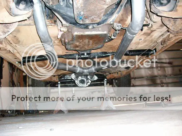
With the headpipes in place I went ahead and built the rest of the exhaust using the Pypes X pipe. You might also notice that the ends of the pipes terminate in ball and socket joints. Even though they can be a bit pricey, this allows to the whole section of pipe to be quickly dropped to remove the crossmember in case I ever have to remove the transmission (a job that would be a real PIA if I had welded all the joints.

HeadXpipe.jpg


headpipeinstallled.jpg


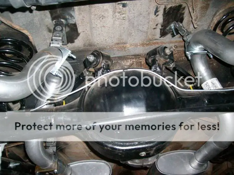
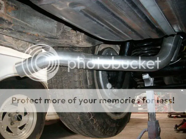
The remainder of the exhaust consisted of a pair of Summit house brand mufflers and the flowmaster tail pipes. The Flowmaster 2 1/2" pipes cleared everything nicely, but because I had decided to add a class III trailer hitch (in part to help tie the rear frame rails together), I modified them to exit behind the tires instead of clear out the back like I had originally planned.

lrtailpipes.jpg


tailpipe.jpg


tailpipetip.jpg
 
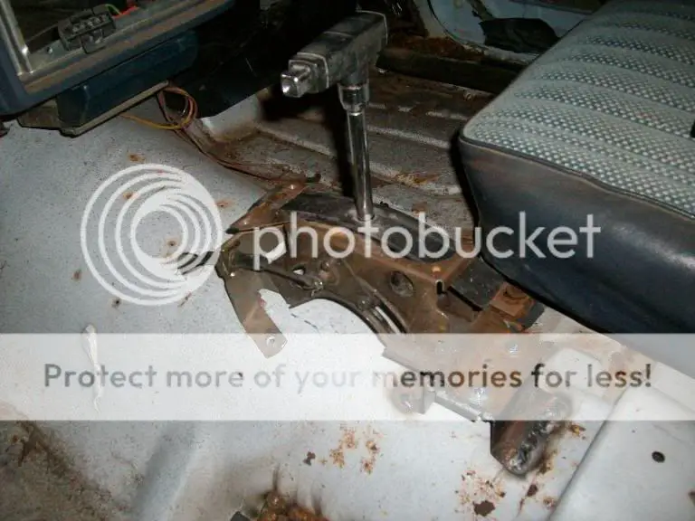
I decided I wanted a floor shifter and console and the shifter installation itself was pretty straight forward as I had picked up the shifter, brackets, cable and transmission brackets.

shifterFbrack.jpg


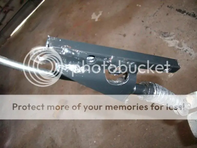
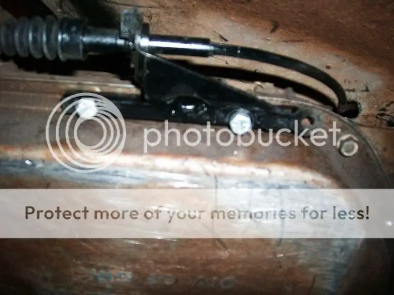
The transmission bracket was for a TH350/TH250 and of course the holes did not line up with the TH400 pan bolts. I solved that issue by welding a small piece of square stock to the bracket (which also serves to replace the factory spacers) and drilling holes to mate to the TH400.

barstock.jpg


transbracketinstalled.jpg


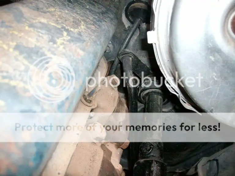
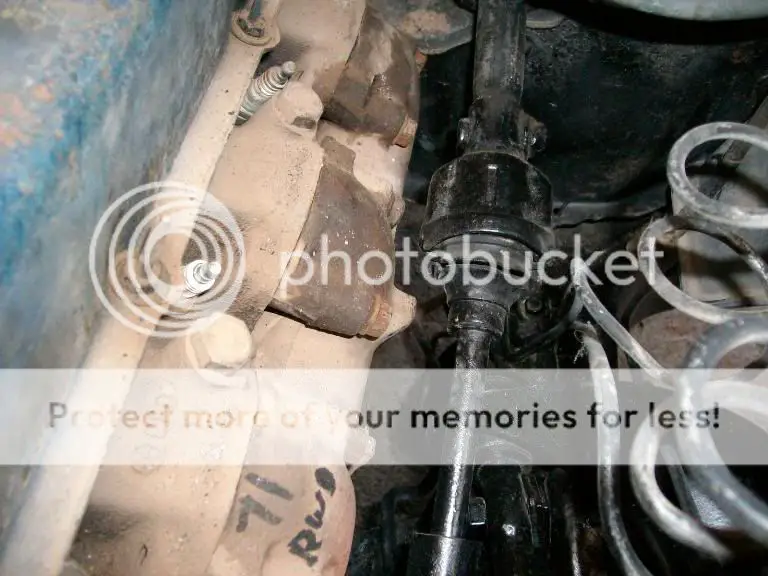
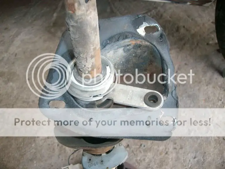
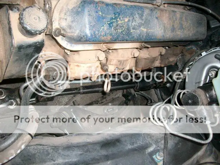
One of the issues when using a floor shift is that the transmission still needs to be connected to the steering column in order to rotate the lower collar in order to have backup lights, neutral safety and steering wheel lock. Unfortunately with the Cadillac swap the rod connecting the column to the transmission is a major interference point with the exhaust manifold and back of the engine.

In order to gain some extra room, I pulled the steering column and elongated the lower mounting holes to move the column a bit to the left. I also found out that some of the G bodies used a 1/4" linkage instead of the 3/8” one that was on the El Camino (I have no idea why, both pieces of linkage came off of column shift cars). These 2 changes did make some extra room but it was still not quite enough. I was able to get the last little bit of clearance I needed by redrilling the lever on the column and the arm on the lower linkage (both must be drilled to keep the proper ratio) moving the whole linkage to the left.

elongatedholes.jpg


3814.jpg


redriledarm.jpg


secondhole.jpg
 
Then it was on to doing all the little things that would be required make it run when the engine was installed for the final time.

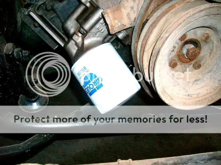
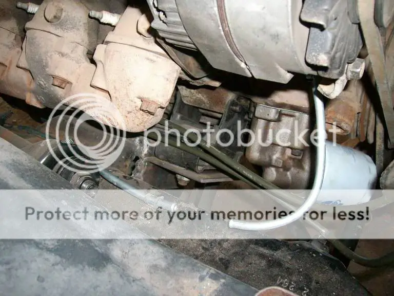
First on the agenda was to change out the oil pump (which is externally mounted on the Cadillac engines) and interferes with the front sway bar. I changed the 73 500 El Dorado oil pump for a later 425 Cadillac pump which tucks the filter in closer to the engine. This provided just enough clearance to clear the front sway bar without spacing the bar (and the lower jounce bars) down. In this picture I had not yet changed out the sway bar bushings which ended up giving a bit more clearance.

GOilPump.jpg


Next was running fuel lines, on the Chevy powered cars the fuel line is on the passenger side, but the Cadillac fuel pump is on the drivers side so I ran a new line from the tank to the pump and after re-routing the original fuel line used it as a return line.

fuelline.jpg


returnlines.jpg


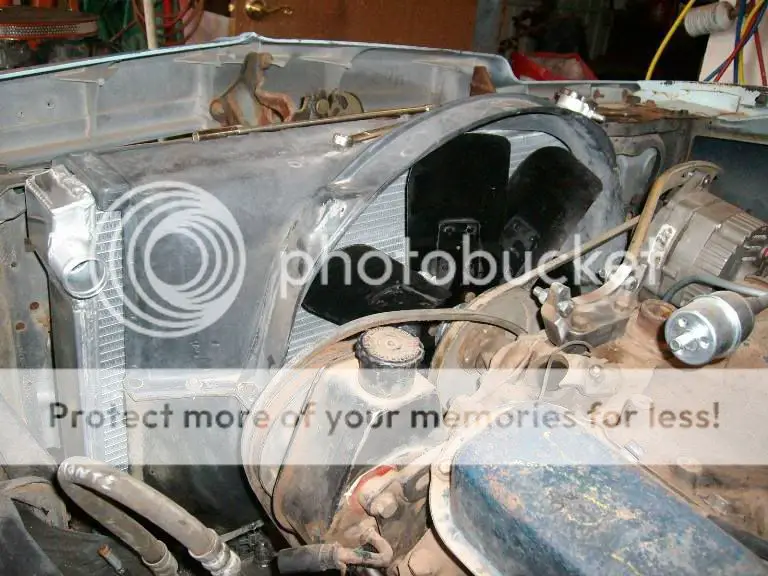
The radiator went in next, I used an aluminium 2 row (1 inch rows) replacement which fit right in the core support, but with the engine sitting to the passenger side I ended up having to also relocate the fan shroud. I decided on using a 7 blade fan with the HD fan clutch, which might be a bit of overkill for most applications but this will be run with the AC in 100+ degree temperature during the summer and every little bit helps.

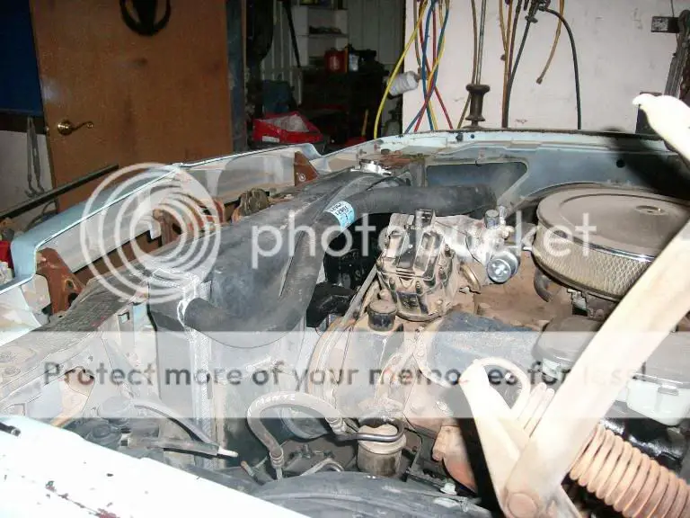
The radiator hoses were pretty straight forward, the upper is a 73 El Dorado hose and the lower was one I picked up off the rack that happened to have the correct bend.

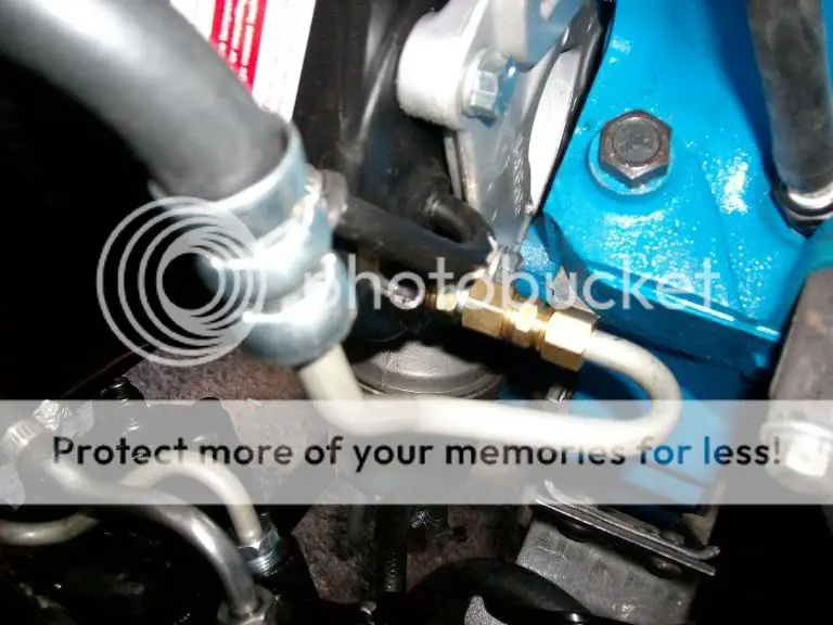
The power steering hose was from an 81 Monte Carlo. Unfortunatly the Cadillac pump uses a compression fitting and the hose is for an O ring. I tried to get by just changing the fitting at the back of the pump, but for some reason when I did the pump did not develop pressure. I ended up putting the old fitting back in and using a compression fitting and flare end to make the hose work with the pump.

relocatedshroud.jpg


fanRadiator.jpg


hoses1.jpg


pumpfitting.jpg


fitting.jpg


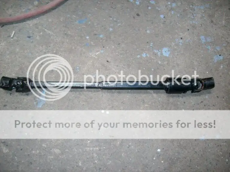
The last couple of things I did were to change the steering shaft over to the Jeep unit with U joints (which really helped tighten the steering feel up and add a bit more steering clearance.

84-96Jeep.jpg


jeepGBody.jpg


shaftin.jpg


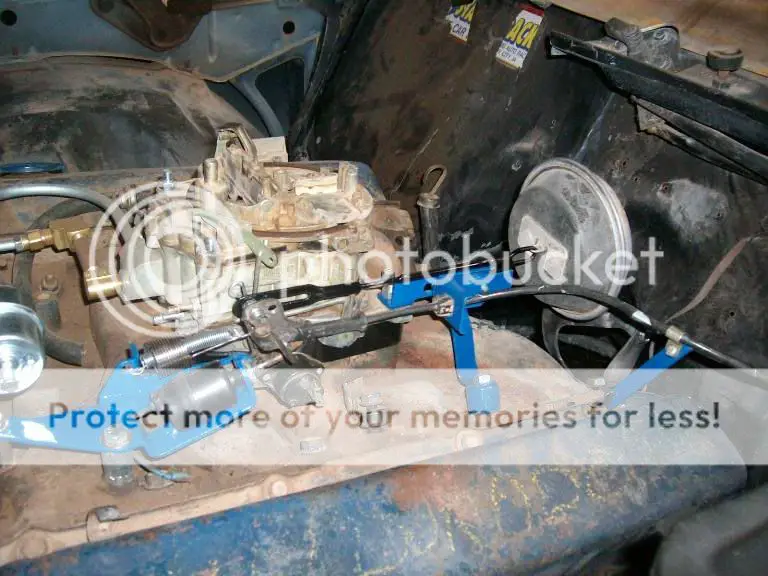
And making spacers for the throttle and kickdown brackets and mounting the vacuum pod for the Cruise Control.

carbbrackets.jpg


At this point everything is in and hooked up and it’s time to take it all apart so the engine and trans can be rebuilt, paint and body work done and reassemble.


engmockup.jpg
 
  • Like
Reactions: Ugly1
And so out came the motor and transmission and the body went off the to body shop

viewtopic.php?f=41&t=25429


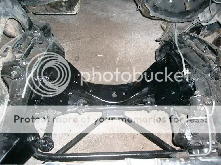
With the engine out the frame mounts for the engine were final welded and a slot cut in the passenger side mount. Gussetts were added to the top and bottom for extra stregnth. The areas that were tight around the exhaust were modified (heat and hammer LOL) and then everything cleaned up and painted.

MotorMounts1.jpg


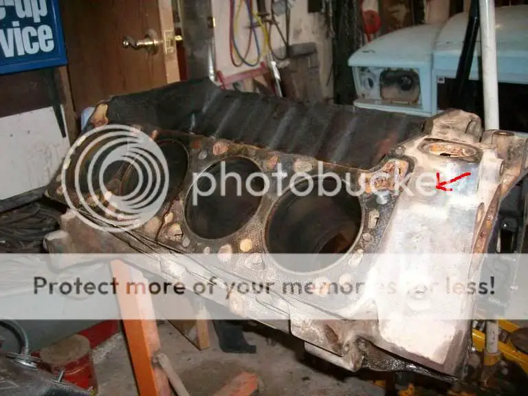
When I tore the engine down I found out it could have probably gotten by with just a set of rings, bearings and a valve job, except that one cylinder had had water in it at some point.....so it ended up being bored .030 (to 507 CI) the crank turned and the valves done. I also drilled and tapped the area indicated to provide hot water for the heater that was more accessible than the stock location located in the back of the block

block.jpg


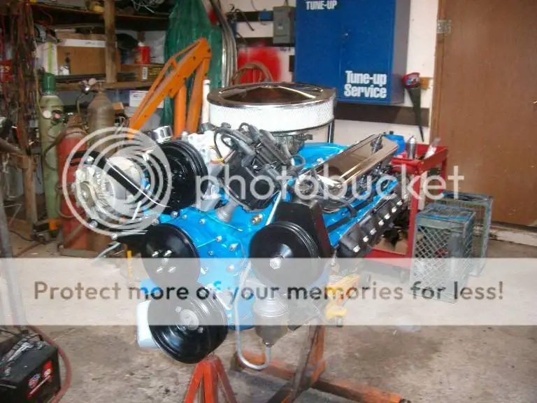
The rebuild itself was pretty straight forward, a .030 over bore and stock style 8.5:1 compression pistons, crank turned .010/.010, a slightly hotter MT 5 cam and better valve springs.

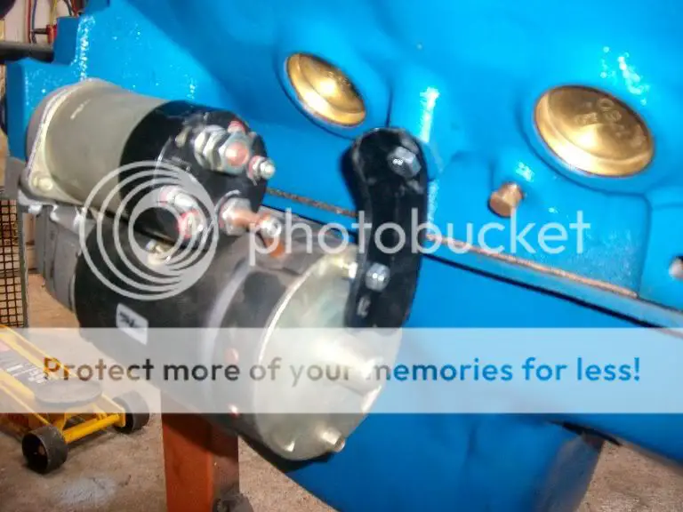
A highly recommended starter brace was also added (you definitely do NOT want 500 cubic inches kicking back on the starter without one).

500built.jpg


Starterbrace.jpg


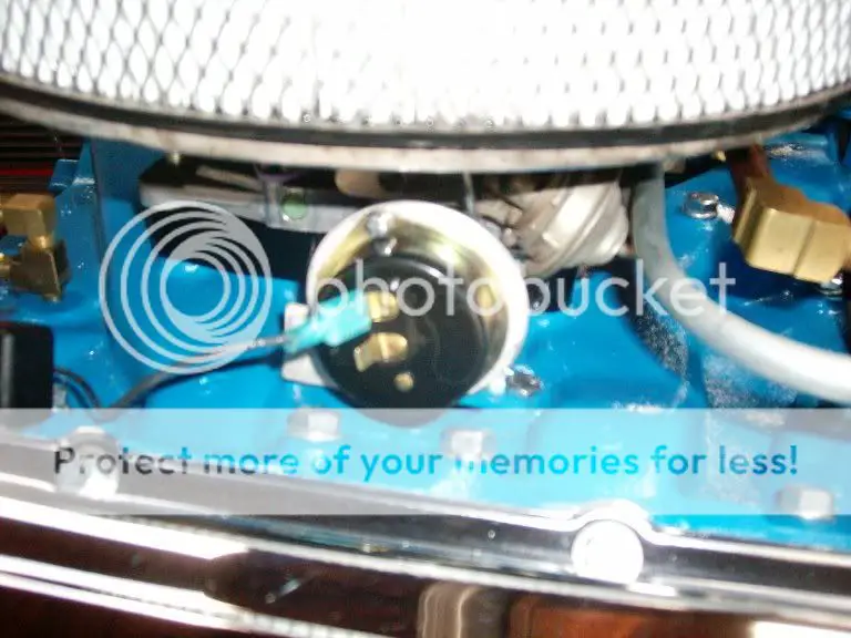
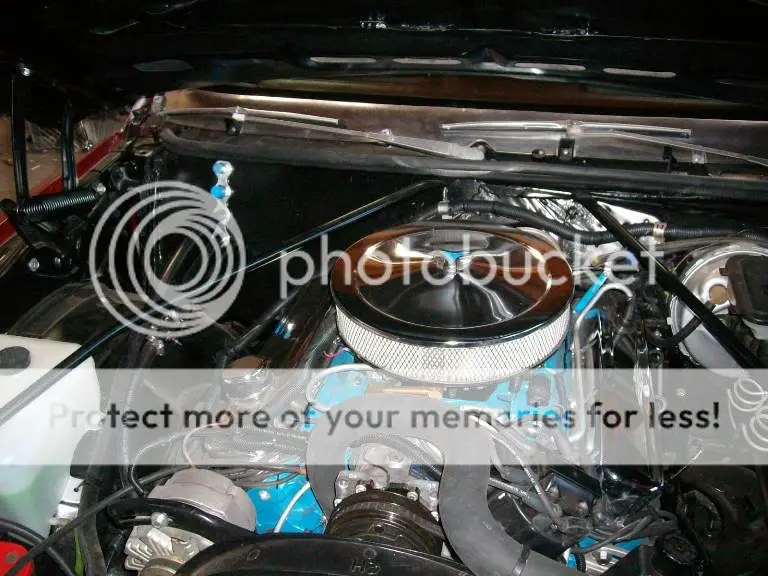
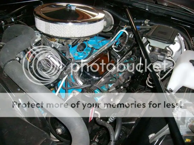
I kept the stock intake and rebuilt the original Q Jet, but also added an electric choke.

choke.jpg


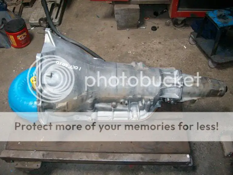
The TH400 was also gone thru and ready to install shortly after I got the engine built.

TH400.jpg


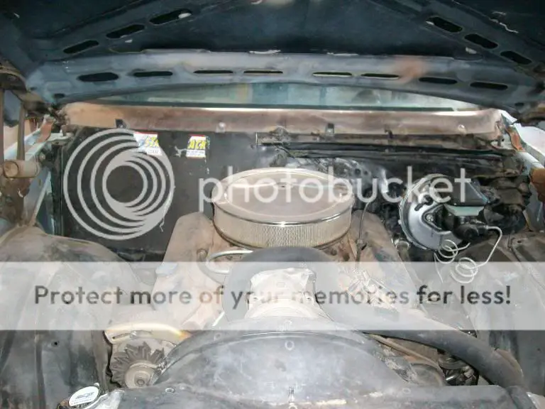
Having already put everything thru mockup it was pretty much just bolting everything back together once I had painted the body.

nohood.jpg


engin.jpg


engfrnt.jpg


drveng.jpg
 
  • Like
Reactions: Ugly1
I’ve put a few hundred miles on the El Camino so far and other than having a problem with the Posi on the initial test drive there have been no issues with it.

I have had my fair share of hot cars over the years and still own a couple and this is a bit different driving experience. Most of my Hot Rods idled a bit on the rough side and really don’t start waking up until they build some RPM. When I launch with either there is an explosiveness to it that reminds me why I own them.

With the 507 Cadillac on the other hand idles smoothly and is extremely well mannered around town. It starts and stays running easily even when it’s below 30 degrees and heats up quickly then stays right at 190 degrees. When I have launched it (after the tires get some traction) it just PULLS, there’s nothing dramatic about it just sets you WAY back in the seat until it’s time to up shift and then it does it all over again. It doesn’t wind nearly as tight as a lot of my previous cars but with the 2.75s it doesn’t have to. Much as I hate to admit it this pretty much stock setup will very likely outrun either of my other 2 current hot rods.......and probably get better mileage in the process.


outside83.jpg

pass83.jpg


The engine swap itself is not overly complicated but it does require a lot of attention to detail to properly place the engine and because of all the little modifications needed to linkages, crossmember fitment etc I wouldn’t classify it as a direct bolt-in or the easiest swap I’ve ever done for me the results were well worth the effort.
 
Hmmm, I can't decide what is cooler. The Caddy engine or the fact that it's an 'ElMonte'. Damn that thing is nice. 8)
 
Wow nice job , Looks great . After seeing what all you did Im glad i went with a Big Block Buick alotta less fabin to do . Two thumbs up man beautiful car.
 

GBodyForum is a participant in the Amazon Services LLC Associates Program, an affiliate advertising program designed to provide a means for sites to earn advertising fees by advertising and linking to amazon.com. Amazon, the Amazon logo, AmazonSupply, and the AmazonSupply logo are trademarks of Amazon.com, Inc. or its affiliates.

Please support GBodyForum Sponsors

Classic Truck Consoles Dixie Restoration Depot UMI Performance

Contact [email protected] for info on becoming a sponsor