MONTE CARLO Can anyone identify these connectors (I think they are AC system related)

Status
Not open for further replies.

samckitt

Not-quite-so-new-guy
Sep 3, 2009
22
7
3
Eastern VA
dYYPLeB.jpg


The connectors in the bottom 2 images, i found disconnected from anything.
z73bXCh.jpg


I think these 2 terminals are supposed to be in the 4 pin connector that has the heavy gauge red wire (top right in first image), but I don't know what that connector mates to either.
XcumiJ3.jpg


I thought the bottom round one went to this sensor, but nope, there is another connector for it.
LGyBO8Z.jpg
 

airboatgreg

Comic Book Super Hero
Oct 2, 2016
2,863
3,112
113
Top pics are AC. Wires normally burn and the connector gets bypassed. Not 100% sure of the middle left but suspect it is an emissions plug on something that was not used on your car. Middle right goes to AC pressure cycling switch.
 

samckitt

Not-quite-so-new-guy
Sep 3, 2009
22
7
3
Eastern VA
The connector you think is emissions plug & the AC pressure cycling switch are on the same harness & are wired like this:
ZFTdMbw.jpg


There is a device on teh accumulator that has a similar round connector as above, but it has a connector on it.
 

383_StealthRam

Greasemonkey
Dec 29, 2016
176
389
63
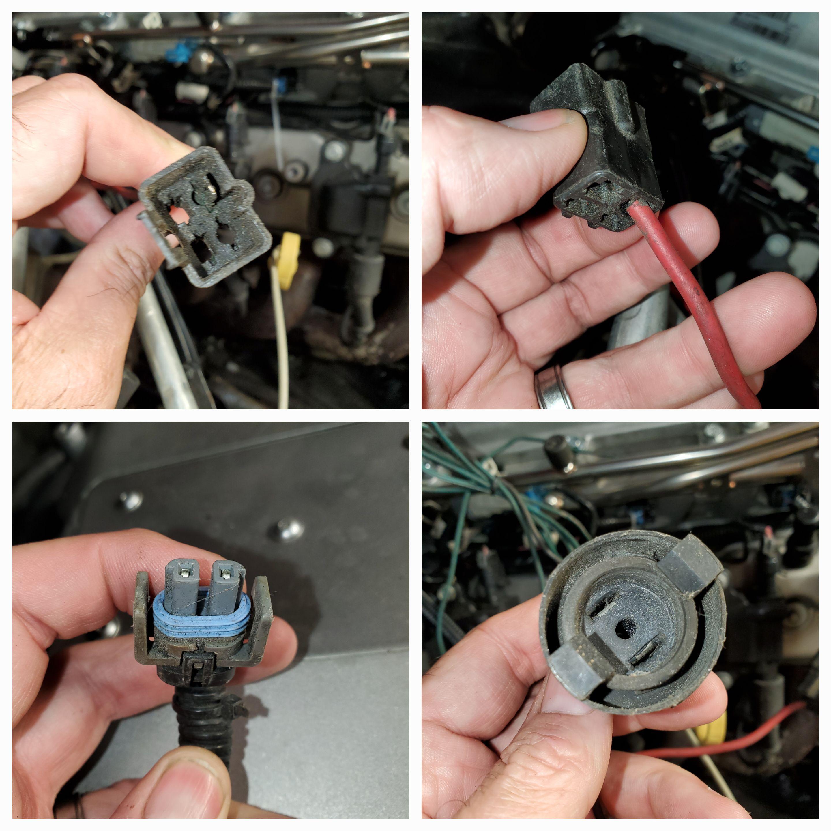
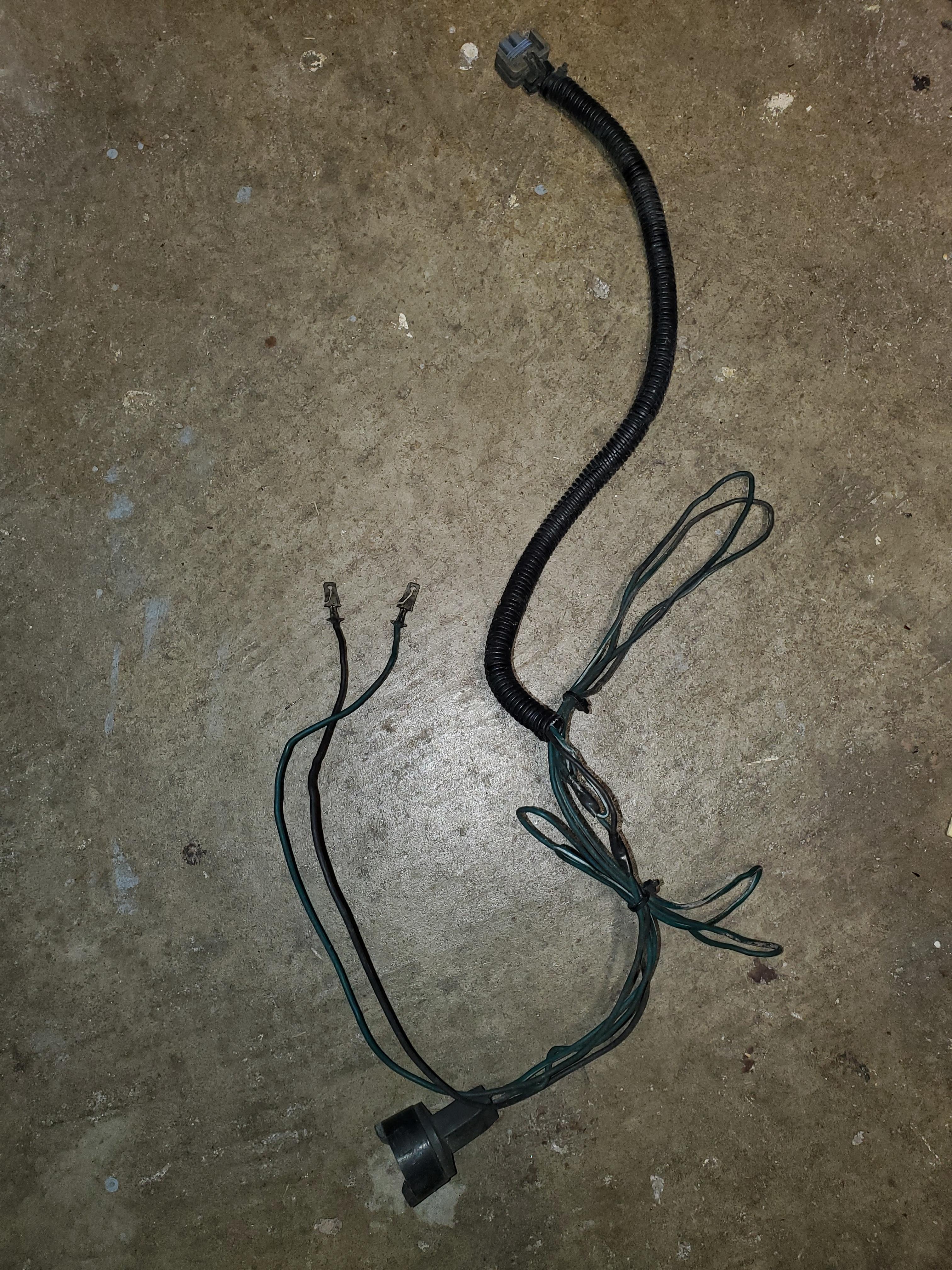
The first 4 plug connector with the heavy gauge red wire is identified as C497, I'm using 87 Cutlass manual, but it should be very similar or even exactly the same as MC, GP, Regal HVAC wiring with RPO C60 (Four Season).

C497 terminal B comes from Fusible Link A (starter solenoid presumably) and goes to the A/C Blower Relay terminal D

1657548085431.png


1657548121676.png


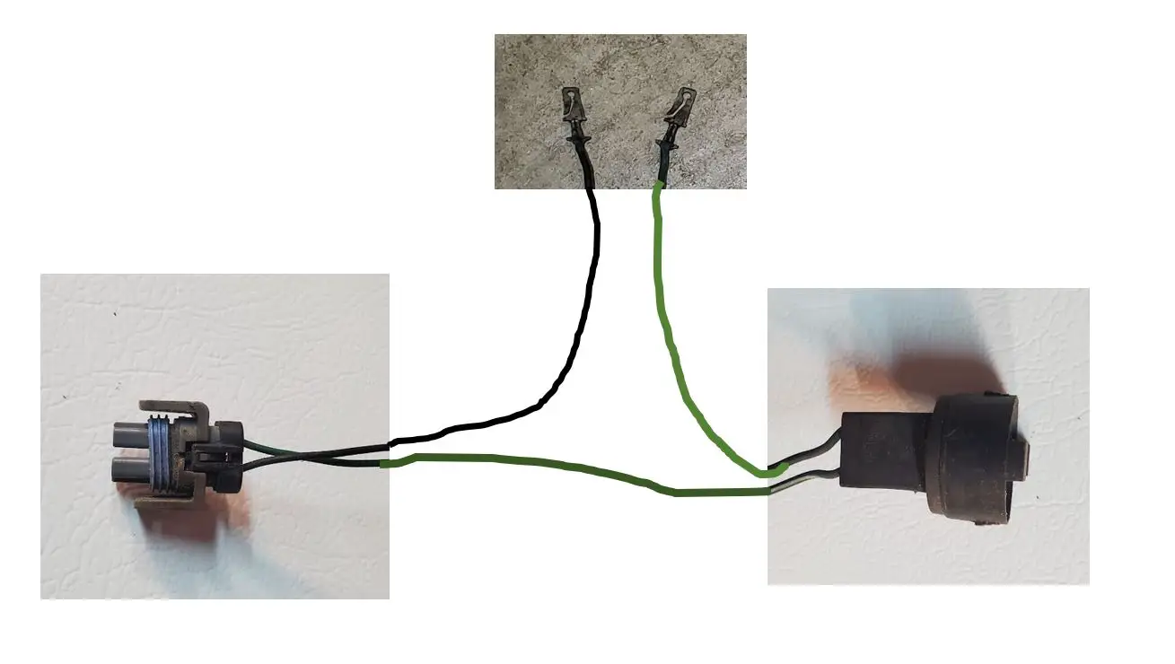
C497 terminal D is the black wire that comes from the Compressor Clutch connector, and provides ground for the clutch coil.
C497 terminal C is the light green wire comes from the dash HVAC control head, and goes to the compressor control relay to provide it power. The ECM controls the compressor by ground that CC relay.

I don't remember but I don't think there's any fourth wire in that C497 connector so it's just an empty cavity. Maybe someone else can chime in if they know.

1657548677527.png


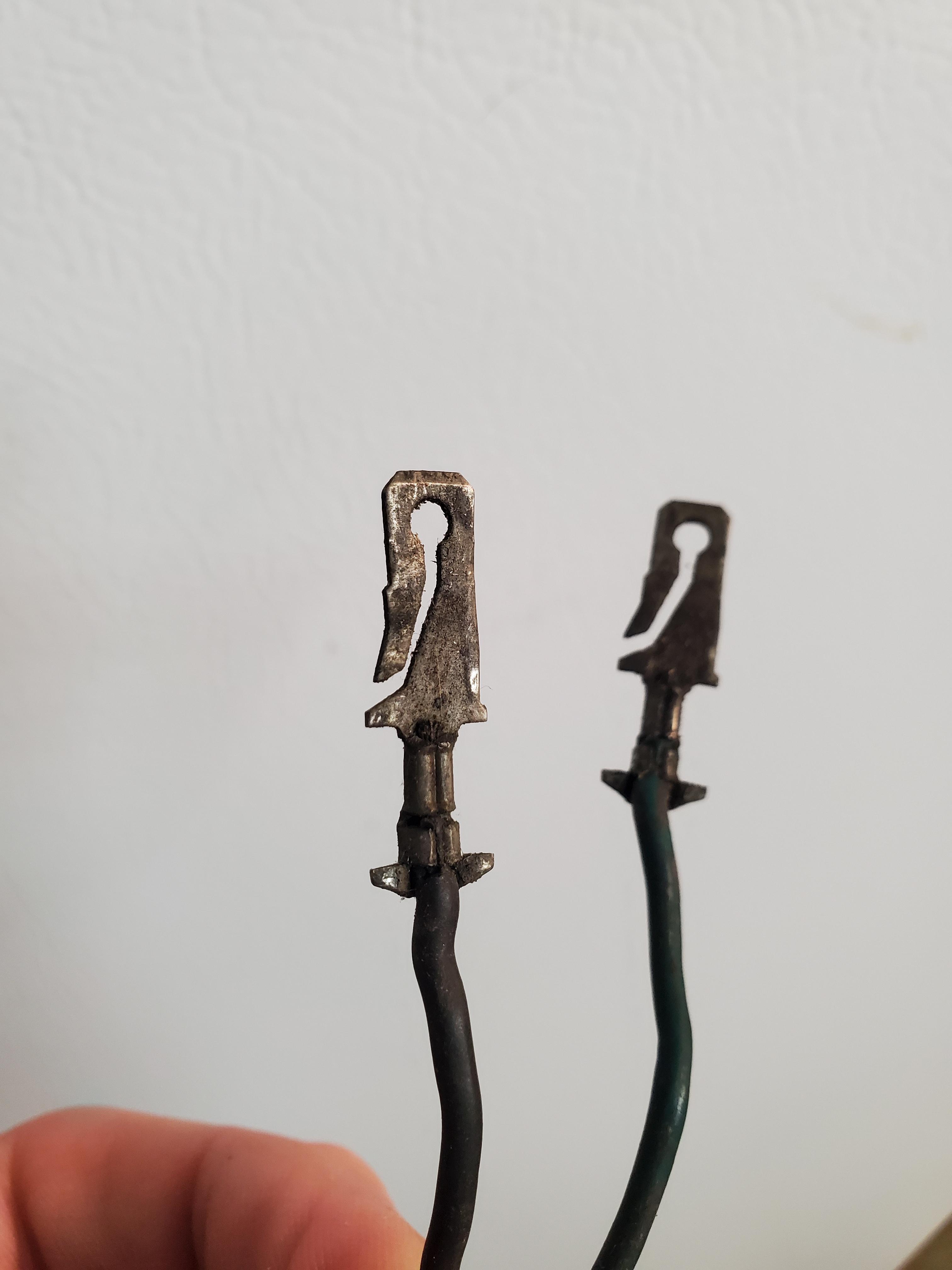
Lastly looking at your compressor clutch connector, that looks like its for a later year R4 compressor that has the metri-pak plug, vs the older one with diode taped inside the tape in the 80's cars. If that's what you have I'm sure you can use it, just be sure it has a diode in the harness, or you can easily change it if you need the older style.


1657549154790.png
1657549794500.png


1657549225035.png
1657549733999.png


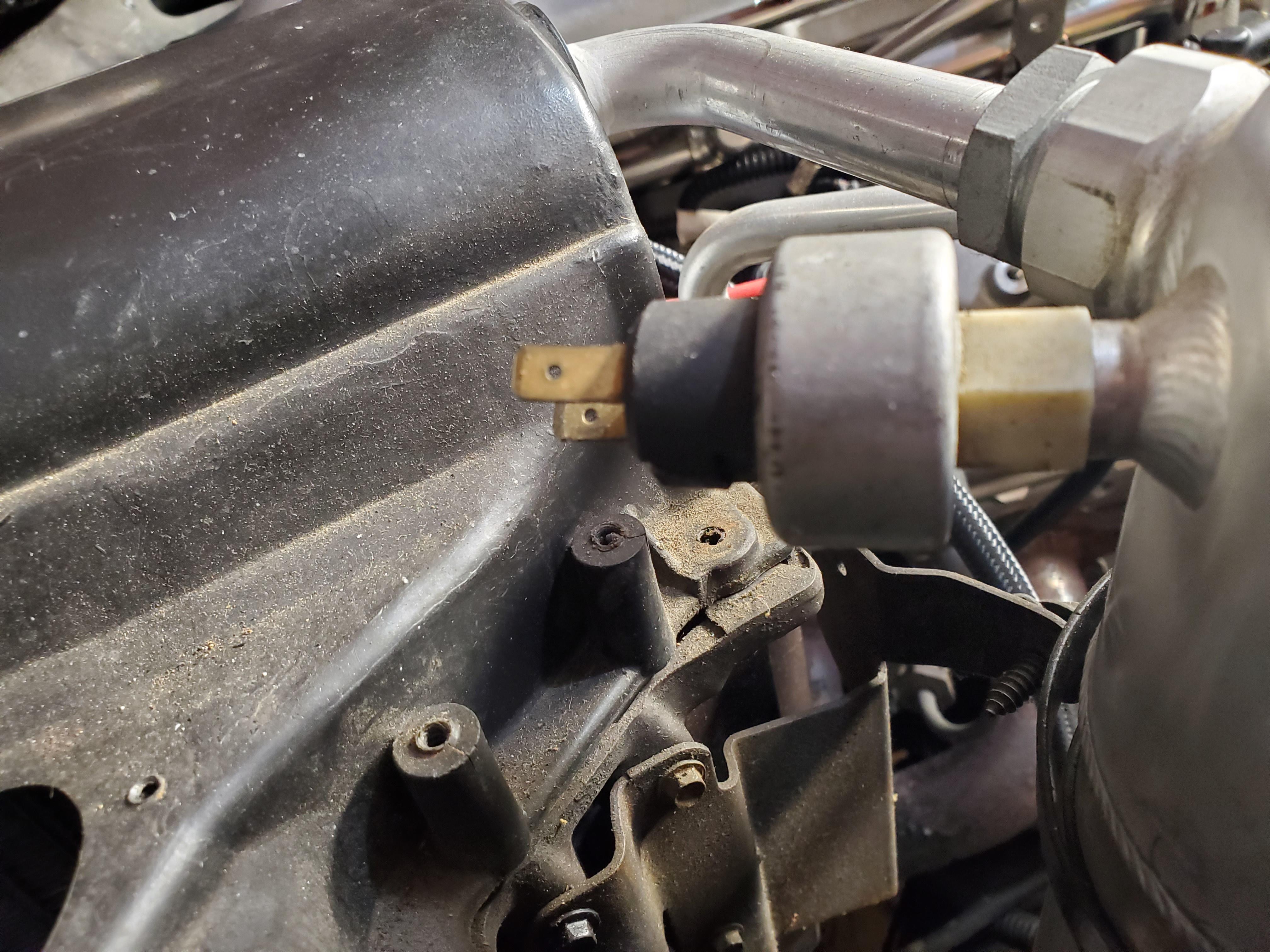
Hopefully this information is helpful. I know there were a few variations on compressor/blower controls on 80's G Bodys depending on carline/engine, etc...but by and large they were mostly similar in control logic. The CCC cars (with ECM controlled carburetors) typically controlled the compressor with a relay and A/C inputs. Compressor safety/cycling (high and low pressure) were typically controlled via hi and low side switches. Early GM used to use thermostatically controlled cycling switches with capillary tube sensors on the evaporator outlet, but I think those were all mostly gone by mid 80's...
 
  • Like
Reactions: 1 user

samckitt

Not-quite-so-new-guy
Sep 3, 2009
22
7
3
Eastern VA
Yes that helps, thanks.

Is there 2 pressure switches that take the round 2 terminal connector? There is one on the Accumulator that has a connector on it. Was there another on a cooling tube/hose somewhere?

I bought this car about 20 years ago with no motor or trans, put an LT1/T56 in it, now has LS motor in it & trying to figure heads or tails of the AC wiring. I am going to have to do some rewiring. The SD7 compressor only has one wire, it is grounded through the engine. And looks like I will have to replace that 4 cavity connector with something else, since i only have half of it.
 

383_StealthRam

Greasemonkey
Dec 29, 2016
176
389
63
As far as I know only one lo side pressure cycling switch, on the accumulator. Some cars had R4 compressors where the compressor clutch was also protected by a hi side pressure switch located directly in the compressor itself. Some had one PIN type connector, later had metri-pak connector but the function was to disable the compressor clutch if the pressure got too high. Most just have a plug stuck in there because they had engine driven fans and it was highly unlikely there wouldn't be enough air moving past the AC condenser. Later cars use them more and more because electric fans could sometimes fail, or not run properly and cause low flow through condenser and jack up the hi side pressures. Some early oem R4 compressors may not even drilled/machined for the switch at all...

Some cars (like F bodys with electric fans) put pressure switches on the high side lines so they could control the secondary fan based off ac system pressure too. I don't think that was the case EXCEPT maybe for the Turbo Regals may have used some variation of that with it's electric fan configuration.

HTH

1657551312426.png
 
Status
Not open for further replies.

GBodyForum is a participant in the Amazon Services LLC Associates Program, an affiliate advertising program designed to provide a means for sites to earn advertising fees by advertising and linking to amazon.com. Amazon, the Amazon logo, AmazonSupply, and the AmazonSupply logo are trademarks of Amazon.com, Inc. or its affiliates.

Please support GBodyForum Sponsors

Classic Truck Consoles Dixie Restoration Depot UMI Performance

Contact [email protected] for info on becoming a sponsor