SBC T56 driveline vibration?

Status
Not open for further replies.

Squag27

Not-quite-so-new-guy
Jun 23, 2021
33
17
8
West Palm Beach FL
So I've had a bear of a time getting rid of a driveline vibration in my '82 as long as I've had my T56 swap and could use some outside input. When I first did the swap I got a Gforce T56 specific crossmember and a set of adjustable rear upper control arms to get the pinion angle right. The shop I had set the pinion angle said they couldn't get the angle right even with the adjustable arms and ended up modifying the crossmember as well as the floor pan to shift the trans up. It didn't really fix the issue though so I moved onto other possibilities. Replacing a plethora of bushings as well as new driveshaft, wheels, and tires helped but hasn't ever solved it. This past year I rebuilt the T56 transmission that's in the car, rebuilt the rear end, and replaced the axles. This basically didn't help and the car still has a droning vibration from 75-85mph, but not so much above or below that. The vibration is also worst at coasting, its still there an acceleration and deceleration but not as bad. I've checked under the car with a stethoscope while it was jacked up, in gear and revved to 75ish mph to try and locate the source of the vibration but I can hear it basically equally in the trans and throughout the rear end. I even did the same with the rear wheels and rotors off with no difference so I've definitely narrowed it down to somewhere in the actual driveline of the car. I took it to another shop I know to see if they couldn't tackle this beast of an issue and they say that a 4 inch aluminum shaft is the way to go to try and fix the issue. My concern with this is the overall lack of clearance that comes with that large of a shaft, especially being that I use the truck to haul things on occasion. Also I'm not excited of the prospect of the increased NVH that comes with such a large aluminum shaft.
Does anyone have any ideas of other things I can check before going the 4inch driveshaft route?
 
Last edited:

ostrich

Master Mechanic
Aug 27, 2012
310
313
63
Ontario, Canada
I have the same setup, but in my 85 Camaro (Fbody), should be the same procedure, just different adjustments. I have a torque arm to set the pinion angle instead of adjustable uppers. I also just went thru this on my 85SS with my 8.8 install. Get yourself a magnetic angle finder, put it on the crank pulley, get the angle (i.e. 5.5*) then put it on the rear end and get the angle (i.e. 6.0*). You want the front to point down, rear to point up. Then adjust the rear uppers until you have 1-2* less on the rear (i.e. 3*) Did this on my Camaro, no vibrations. I watched this video.
On another note, when I first put my T56 in my Camaro (with a SBC) I had a poly transmission mount (Energy suspension). For years I couldn't get rid of a vibration, switched back to a stock rubber mount, 100% difference. Not sure why, but still have in in there today, no vibrations.
 
  • Like
Reactions: 1 users

Built6spdMCSS

Geezer
Jun 15, 2012
5,803
9,715
113
Florida Beach
LT or LS T56 would be the same here given how the T56 is, rear pinion angle needs to match the driveshaft angle coming out of the trans or be close to it from my experience.
 
  • Agree
Reactions: 1 user

81cutlass

Comic Book Super Hero
Feb 16, 2009
4,649
13,565
113
Western MN
New driveshaft? How much yoke engagement? Straight 1310/1350 u joints or conversion units?

I have an LT1 t56 behind my lq4. The G body trans tunnel isn't technically tall enough to get 'optimum' angle and the back of the trans will sag a bit lower than a stock auto.

If your rear end pinion angle is generally opposite and equal and not insane (like 10+ degrees) the only thing optimal angle gains you is some U joint life.

You need to get the trans as high as you can if you are going to solve it.

I had wicked driveline vibration when I first put the setup together. I had a used nascar driveshaft and cheapish clutch. It got better when I got a new driveshaft, better again when I tweaked my pinion angle, and again better when I swapped the clutch from a cheapish one to a better one.

If your rear doesn't have adjustable uppers I'd start there and try a few different positions to see if it gets better or worse.

Mine vibrated really bad at moderate/high highway speed engine braking decel but didn't under acceleration. It also shook, less but still did, when coasting in neutral.

Any conditions where it's worst?
 
  • Like
Reactions: 1 user

Squag27

Not-quite-so-new-guy
Jun 23, 2021
33
17
8
West Palm Beach FL
New driveshaft? How much yoke engagement? Straight 1310/1350 u joints or conversion units?

I have an LT1 t56 behind my lq4. The G body trans tunnel isn't technically tall enough to get 'optimum' angle and the back of the trans will sag a bit lower than a stock auto.

If your rear end pinion angle is generally opposite and equal and not insane (like 10+ degrees) the only thing optimal angle gains you is some U joint life.

You need to get the trans as high as you can if you are going to solve it.

I had wicked driveline vibration when I first put the setup together. I had a used nascar driveshaft and cheapish clutch. It got better when I got a new driveshaft, better again when I tweaked my pinion angle, and again better when I swapped the clutch from a cheapish one to a better one.

If your rear doesn't have adjustable uppers I'd start there and try a few different positions to see if it gets better or worse.

Mine vibrated really bad at moderate/high highway speed engine braking decel but didn't under acceleration. It also shook, less but still did, when coasting in neutral.

Any conditions where it's worst?
I'd forgotten to check what the pinion angle is currently set by the most recent shop but last I checked the trans was right around zero degrees and the rear end was pointed down I believe 2 degrees. My floor pan was cut and modified a good bit to clearance the trans. I'll have to check it again though. I do have adjustable uppers but this most recent shop is claiming that they don't have enough adjustment out of the uppers to get the proper pinion angle if the trans were brought back down to where it was before the first shop modified the crossmember. The reason I asked about LT/SBC swaps specifically is I don't know if the LS engines use the same height mounts as stock SBC so who's to say if an off the shelf crossmember will work out of the box.
As I understand it the trans is supposed to be pointed down and the rear is supposed to be pointed up right?
 

scoti

Royal Smart Person
Sep 5, 2019
1,979
3,404
113
Texas
I'd forgotten to check what the pinion angle is currently set by the most recent shop but last I checked the trans was right around zero degrees and the rear end was pointed down I believe 2 degrees. My floor pan was cut and modified a good bit to clearance the trans. I'll have to check it again though. I do have adjustable uppers but this most recent shop is claiming that they don't have enough adjustment out of the uppers to get the proper pinion angle if the trans were brought back down to where it was before the first shop modified the crossmember. The reason I asked about LT/SBC swaps specifically is I don't know if the LS engines use the same height mounts as stock SBC so who's to say if an off the shelf crossmember will work out of the box.
As I understand it the trans is supposed to be pointed down and the rear is supposed to be pointed up right?
Only on 'standard/generic' apps where the differential is lower vs. the trans output shaft. With a standard application, the pinion pointed up toward the trans output shaft is simply trying to minimize the difference between the two angles. In this scenario the driveshaft is higher in the front than it is @ the rear on the vehicle.

Lowered cars/cars that don't have as much variation between the heights or are on the same level (trans output/pinion) can/do change how it works. Tilting the pinion up the same amount as the trans output can yield excessive working angles depending on their location related to one another.

Industry standard w/carb'd motors & shop built hot-rods was 3° tilt to keep the carb floats level while clearing most floor pans. FI set-ups have wiggle room here. You want the rear pinion angle as close to what the crank/trans output is for minimal u-joint bearing working angles. You want to target <2° but >0°. Driveline industry guys say there needs to be slight angle to help the needle bearings rotate to prevent wear.

So in an industry standard application w/the motor @ 3° (trans output shaft pointing down 3°) & the rear end pinion located several inches below the motor/trans height, you tilt the pinion up so it's @ 2° resulting in 3° - 2° = 1° working angle. This is good. In this scenario the driveshaft is higher in the front than it is @ the rear.

The issue is when the two ends are MUCH closer to or on the same plain. When that is the scenario (motor/trans output @ the same level as the pinion), the motor is still @ 3° & the pinion is still @ 2° but it's now 3° + 2° = 5° working angle for the joints. In this scenario the driveshaft can be lower in the front than it is @ the rear & where the math changes. Extreme dropped truck guys encounter this scenario a lot. This is where the driveshaft angle does matter because it impacts the math. As stated in the BMR video, the type of suspension bushings impact the fudge factor you work within as well. Vehicles w/more wiggle room have increased numbers vs. those w/tighter suspensions.
 
  • Like
Reactions: 1 users

Squag27

Not-quite-so-new-guy
Jun 23, 2021
33
17
8
West Palm Beach FL
Only on 'standard/generic' apps where the differential is lower vs. the trans output shaft. With a standard application, the pinion pointed up toward the trans output shaft is simply trying to minimize the difference between the two angles. In this scenario the driveshaft is higher in the front than it is @ the rear on the vehicle.

Lowered cars/cars that don't have as much variation between the heights or are on the same level (trans output/pinion) can/do change how it works. Tilting the pinion up the same amount as the trans output can yield excessive working angles depending on their location related to one another.

Industry standard w/carb'd motors & shop built hot-rods was 3° tilt to keep the carb floats level while clearing most floor pans. FI set-ups have wiggle room here. You want the rear pinion angle as close to what the crank/trans output is for minimal u-joint bearing working angles. You want to target <2° but >0°. Driveline industry guys say there needs to be slight angle to help the needle bearings rotate to prevent wear.

So in an industry standard application w/the motor @ 3° (trans output shaft pointing down 3°) & the rear end pinion located several inches below the motor/trans height, you tilt the pinion up so it's @ 2° resulting in 3° - 2° = 1° working angle. This is good. In this scenario the driveshaft is higher in the front than it is @ the rear.

The issue is when the two ends are MUCH closer to or on the same plain. When that is the scenario (motor/trans output @ the same level as the pinion), the motor is still @ 3° & the pinion is still @ 2° but it's now 3° + 2° = 5° working angle for the joints. In this scenario the driveshaft can be lower in the front than it is @ the rear & where the math changes. Extreme dropped truck guys encounter this scenario a lot. This is where the driveshaft angle does matter because it impacts the math. As stated in the BMR video, the type of suspension bushings impact the fudge factor you work within as well. Vehicles w/more wiggle room have increased numbers vs. those w/tighter suspensions.
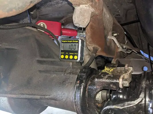
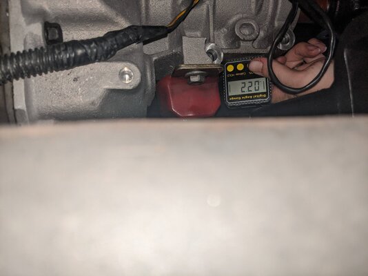
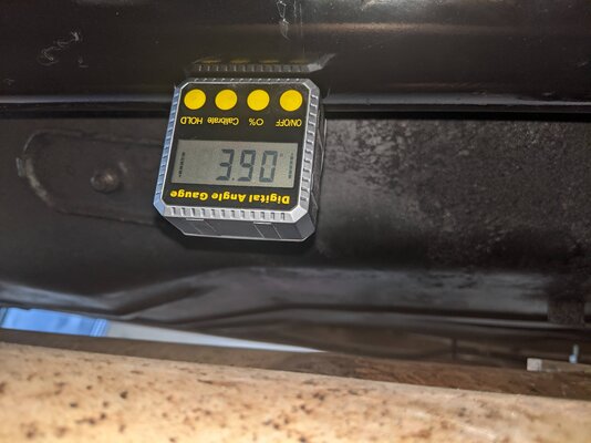
Well just for reference, I rechecked the pinion angles with my digital angle finder over my break and found that the trans appears to be pointed 2 degrees down (measured at the flat spot under the output seal), the pinion is 1 degree up (measured at the flat on the top of the 8.5 rear behind the pinion yoke), and the driveshaft is measuring 3.9 degrees. How does that sound to you?
 

Attachments

  • PXL_20211116_173949636.jpg
    PXL_20211116_173949636.jpg
    1.3 MB · Views: 113
  • PXL_20211116_175429490.jpg
    PXL_20211116_175429490.jpg
    881.2 KB · Views: 106
  • PXL_20211116_173417205.jpg
    PXL_20211116_173417205.jpg
    774.7 KB · Views: 105

81cutlass

Comic Book Super Hero
Feb 16, 2009
4,649
13,565
113
Western MN
1 degree different isn't going to induce a vibration. You need to be in the multiple 3+ range to begin to get anything.

Your locations measuring are a little innacurate due to casting draft but close enough to rule anything super wrong there.

How do your U joints feel? Can you see any wear offset to the slip yoke on the OD?
 
  • Agree
Reactions: 1 users

scoti

Royal Smart Person
Sep 5, 2019
1,979
3,404
113
Texas
Well just for reference, I rechecked the pinion angles with my digital angle finder over my break and found that the trans appears to be pointed 2 degrees down (measured at the flat spot under the output seal), the pinion is 1 degree up (measured at the flat on the top of the 8.5 rear behind the pinion yoke), and the driveshaft is measuring 3.9 degrees. How does that sound to you?
That's within the window of the working angles you would want: 2.2° - 1.0° = 1.2° difference since the driveshaft is higher in the front vs. rear. There is still room for decreasing that target if you're still sensing vibrations but you def seem to be within range. I'm assuming the numbers were pulled w/full weight on the chassis? Confirm your trans number by comparing w/the crank pulley.

Now.... Keep in mind that angles on joints are impacted on both the vertical & horizontal plains. Verify your C/L of the trans output shaft vs. the C/L of the pinion using the frame rails for reference. You'll want a similar tight dimension there as well. This is often over looked yet it's a common issue to have the rear not centered.
 
  • Like
Reactions: 1 users
Status
Not open for further replies.

GBodyForum is a participant in the Amazon Services LLC Associates Program, an affiliate advertising program designed to provide a means for sites to earn advertising fees by advertising and linking to amazon.com. Amazon, the Amazon logo, AmazonSupply, and the AmazonSupply logo are trademarks of Amazon.com, Inc. or its affiliates.

Please support GBodyForum Sponsors

Classic Truck Consoles Dixie Restoration Depot UMI Performance

Contact [email protected] for info on becoming a sponsor