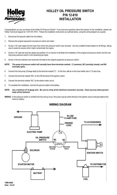
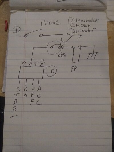
Their diagram will work, their switch is marked, yet it seems to show that pump is energized by cranking, then control passes to the oil pressure switch after engine starts. It shows that priming of the system is done during cranking, which might be a problem, but maybe not. Won't know until it's tried.
It then shows power going to the coil and then the distributor. The coil works on the ground side and this is true for solid state or a points system. If your HEI is going to be connecting through its current GM method path, It should work just fine. No wiring to the distributor needs changed in that event.
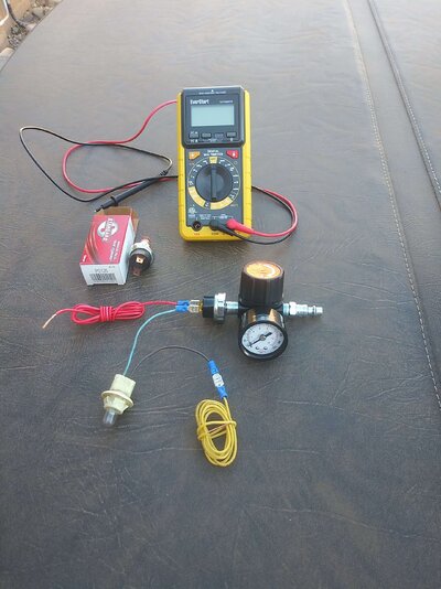
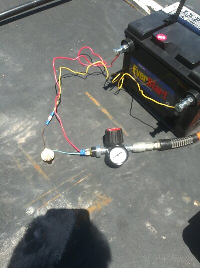
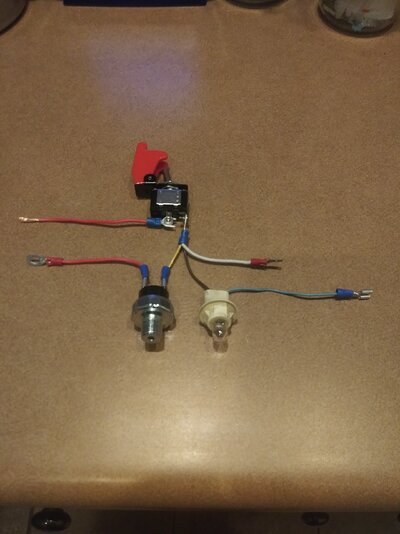
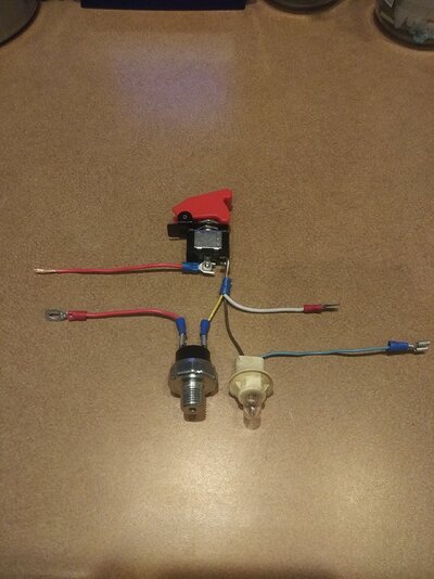
Pics below is simple hook up, although it just the hard wire setup, when in reality it needs a fuse and should have a power relay. For simplicity sake, pics below. The manual switch primes and then once the engine starts you shut off the switch. Once the engine is running, 12vdc power to the pump goes through the oil pressure switch (OPS). The light is just in the circuit as an example of load, in reality the fuel pump would be replacing where the lamp is.
The extra white wire coming out of the switch can be omitted if not needed. The brown wire would be connected to the OPS, but I ran out of connectors. Electrically the way it is wired it's the same.
The priming switch by passes the OPS until the engine is running, then after engine starts it is shut off, 12vdc moves through the OPS to keep FP running.