BUILD THREAD 1987 Olds 442 Project Build

Back with an update.

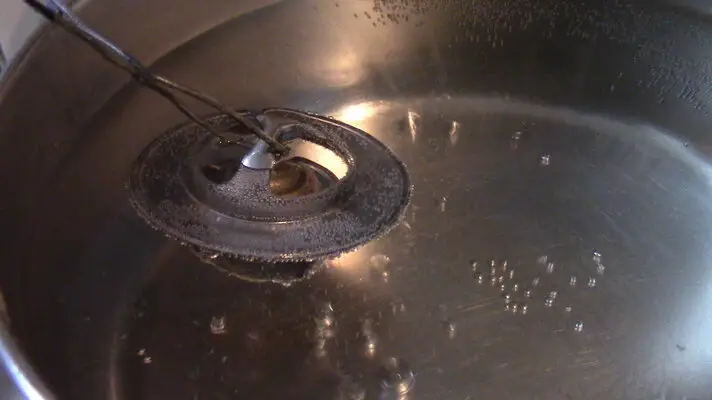
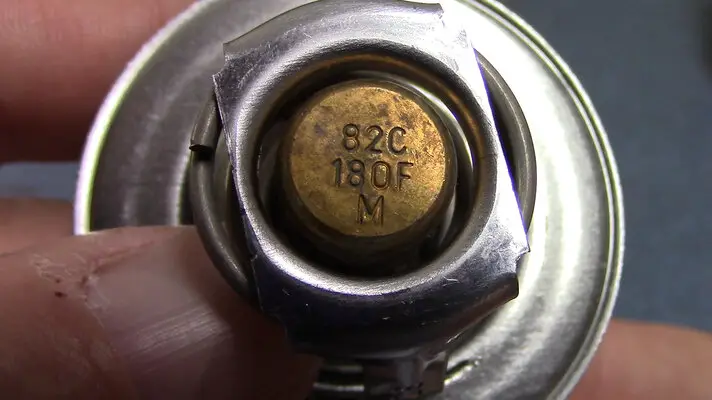
I check my thermostat before installing. It's marked 180 degree, and it opened at 183. Not too bad.
MVI_1774.00_05_05_22.Still001.jpgMVI_1774.00_02_07_59.Still008.jpg

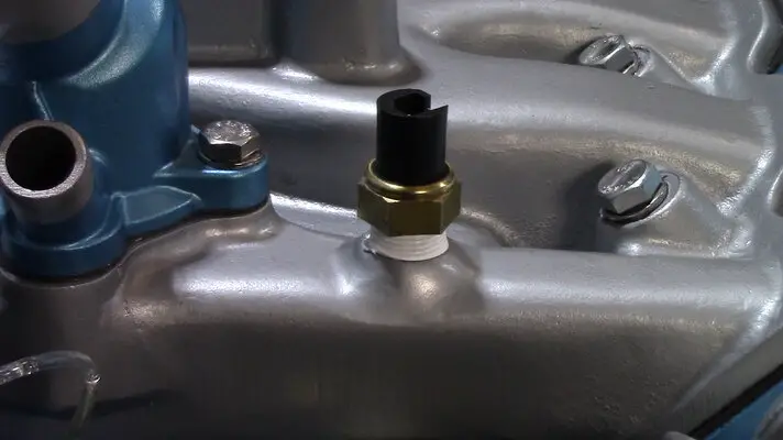
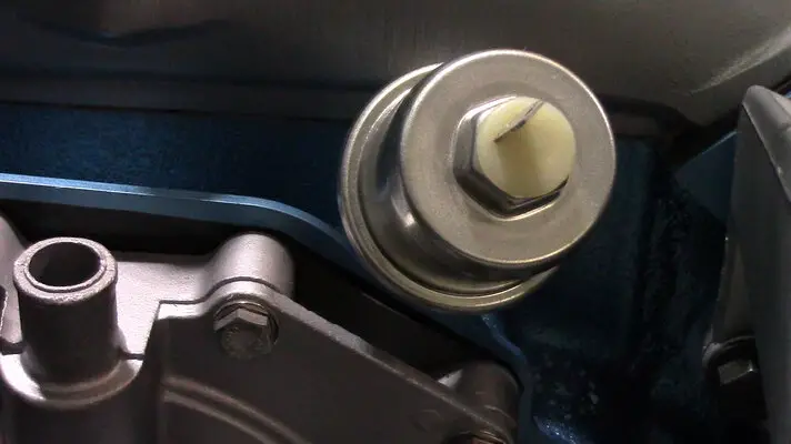
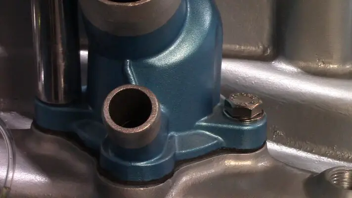
I get the Thermo Housing installed along with a few sensors I'll need in place to finish the harness.
MVI_1774.00_07_49_24.Still010.jpgMVI_1774.00_09_51_19.Still011.jpgMVI_1774.00_11_33_32.Still012.jpg

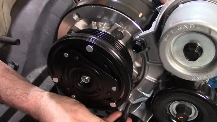
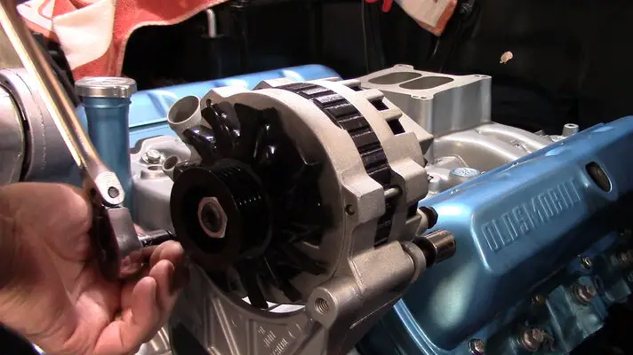
I then install the Alt and Compressor, since they both have wiring hookups I'll need in place.
MVI_1774.00_12_25_51.Still013.jpgMVI_1774.00_16_56_45.Still014.jpg

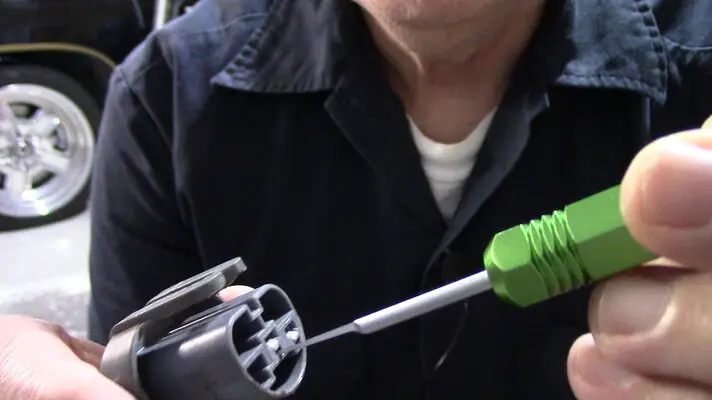
I ended up using the factory headlight connectors since the replacements had a different style terminal.
MVI_1774.00_20_00_25.Still016.jpgMVI_1774.00_22_08_24.Still017.jpg

I lay down all the 12 awg power and grounds along with the 2 relays to begin building the harness.
MVI_1774.00_27_39_24.Still018.jpg


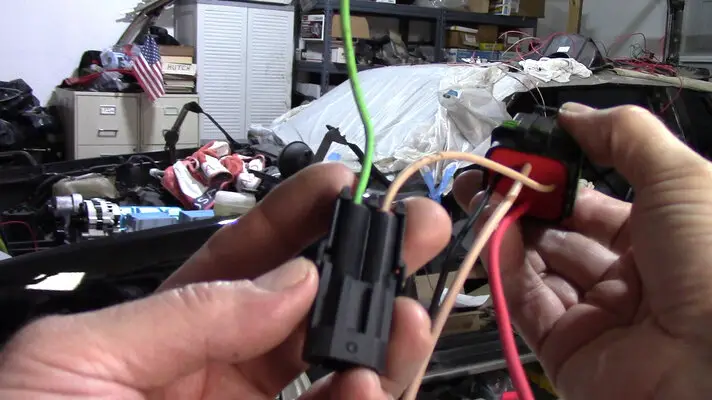
The 12 awg 280 terminals are a close fit in the housings, but not too bad. I had to stretch the 16 awg rubber weather boots on the 12g wire and then shove them in the back of the connector independent of the terminal.
MVI_1774.00_30_53_35.Still019.jpg


Cont.......
 
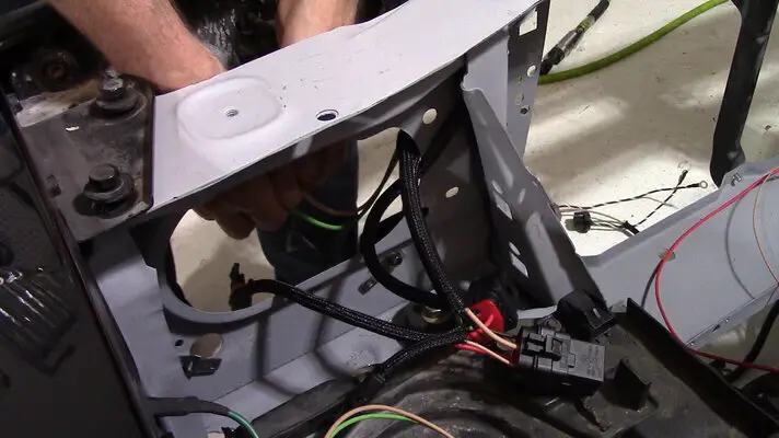
I picked the core support behind the battery as my spot to place the relays.
MVI_1774.00_36_37_50.Still020.jpg


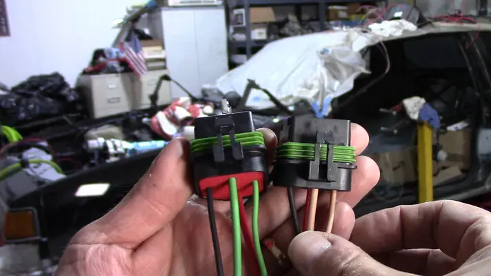
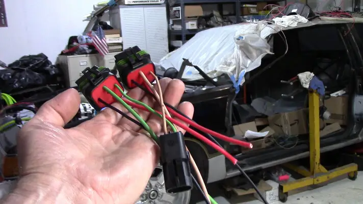
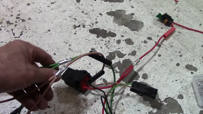
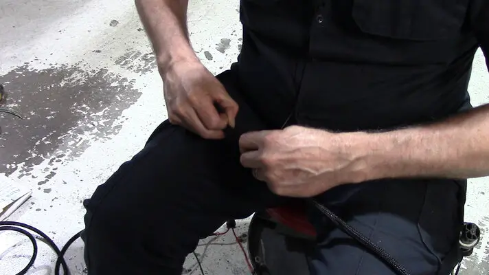
I build the harness and relay connectors with serviceability in mind by adding a 2 wire weather pack connector to be able to disconnect it from the main harness.
MVI_1774.00_42_22_04.Still002.jpgMVI_1774.00_41_38_50.Still022.jpgMVI_1774.00_43_15_10.Still003.jpg

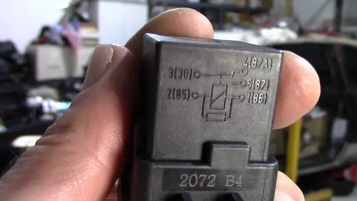
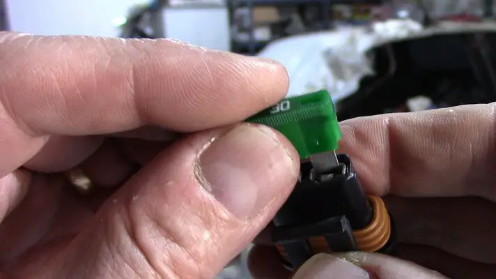
I'm using 40 amp relays with a 30 amp inline fuse holder.
MVI_1774.00_40_51_33.Still001.jpgMVI_1774.00_43_30_36.Still004.jpg

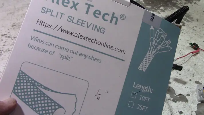
It's mostly a 2 wire harness, so I use 1/4" braided loom.
MVI_1774.00_44_21_14.Still005.jpgMVI_1774.00_44_09_34.Still023.jpg

With all the heat shrink installed over the butt connectors and ring ends and the loom over that, I do a last test fit of the harness.
MVI_1774.00_44_52_07.Still024.jpgMVI_1774.00_47_35_25.Still025.jpg
MVI_1774.00_48_38_56.Still006.jpg


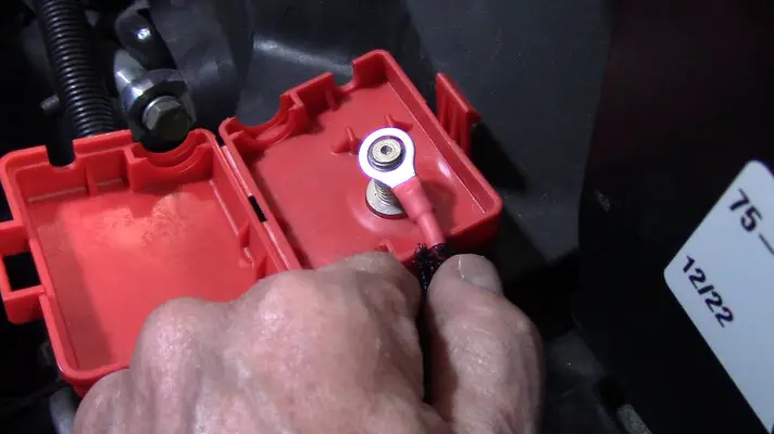
The relays will be connected to a GM Positive Cable Junction Block I installed by the battery on the inner fender.
MVI_1774.00_52_53_10.Still007.jpg

Hutch
 
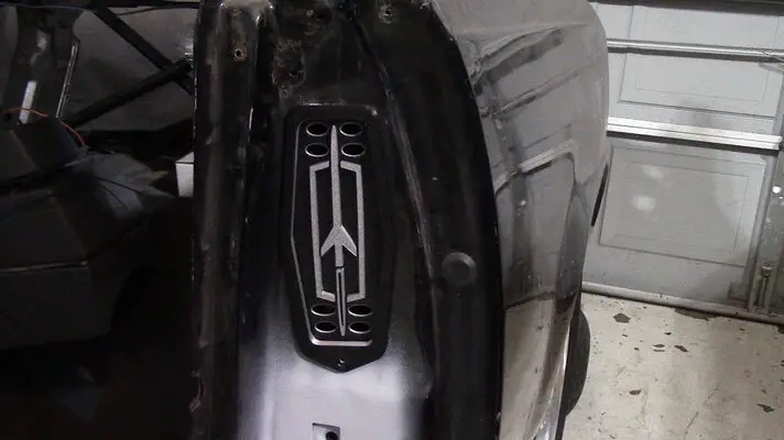
I got these custom door jamb vents from Sharky and I couldn't be more over the moon with how they turned out!

Beautiful!!
Rocket Door Jamb.jpg

MVI_1839.MP4.00_00_07_58.Still002.jpg

Thanks brother!

Hutch
 
I've been lazy! Time to play catch up.

I finished the harness. Here's where I left off.

I made a separate harness for the starter. This way I can unplug it and have it go with the engine during an engine pull. (hopefully never)

I use a fiberglass heat shield to run the wires through.
Heat Fiberglass Shield.jpg

MVI_1842.00_04_55_16.Still003.jpg

MVI_1842.00_09_35_49.Still001.jpg

MVI_1842.00_11_39_12.Still002.jpg

MVI_1842.00_14_27_27.Still001.jpg


It all goes in a starter heat wrap shield.
MVI_1842.00_18_45_27.Still004.jpg

MVI_1842.00_22_33_32.Still006.jpg


I'll run the wires up to a high amp (46 amp) connector.
MVI_1842.00_25_25_31.Still007.jpg

MVI_1897.00_05_33_48.Still001.jpg

MVI_1897.00_06_32_34.Still002.jpg


Hutch
 
The Battery wire from the Batt to the Junction Box.
MVI_1842.00_32_50_15.Still008.jpg

MVI_1842.00_33_05_25.Still009.jpg

MVI_1842.00_33_12_54.Still010.jpg

MVI_1842.00_33_35_20.Still011.jpg

MVI_1842.00_33_42_49.Still012.jpg


I run the cable around the back of the battery to the junction box.
MVI_1842.00_34_50_07.Still013.jpg

MVI_1842.00_37_04_43.Still014.jpg


Crimp and heat shrink.
MVI_1842.00_40_45_54.Still017.jpg


That junction is getting full.
MVI_1842.00_42_25_59.Still018.jpg


Hutch
 
Turn Signals and Marker Lights

I take this jumble of wires and trace all the splices and connectors.
MVI_1897.00_09_11_24.Still002.jpg


From that, I make a simplistic wiring diagram to build the circuits.
MVI_1897.00_10_37_11.Still001.jpg


On goes the front bumper to be able to get the wire lengths right.
MVI_1897.00_05_06_08.Still001.jpg


I put a 3 wire connector just in front of the core support to be able to remove the light harness separately.
MVI_1897.00_14_04_53.Still003.jpg


Then it's just a matter of cutting and splicing wires to the new connectors.
MVI_1897.00_17_05_12.Still002.jpg


Hutch
 
On the the A/C Power side (Connector C497)

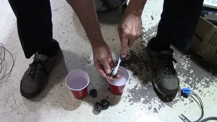
I install the blower relay and clean and check the connector wires.
MVI_1897.00_35_50_54.Still004.jpg

MVI_1897.00_43_53_21.Still005.jpg

MVI_1897.00_43_58_22.Still006.jpg


I use a pic from my phone to get the wires installed correctly into the connector.
MVI_1897.00_44_08_20.Still007.jpg


I refer to the Shop Manual for my wiring change.
MVI_1897.00_25_46_02.Still005.jpg

MVI_1897.00_25_49_59.Still006.jpg


Since I'm not using the ECM, I get rid of the Compressor Control Relay and wire the Lt Green trigger wire at C497 straight to the Lt Green/Black Compressor Clutch wire. The compressor will then be controlled by me and the A/C Pressure Cycling Switch.
MVI_1897.00_25_49_59.Still006 - Copy.jpg


I get rid of the C497 connector that usually is draped over the passenger side valve cover (and sometimes melts or overheats) and will instead run it behind the fender to exit out by the evap canister. I will then use a 47 amp weather pack connector.
MVI_1897.00_23_32_10.Still011.jpg

MVI_1897.01_02_12_29.Still010.jpg


Hutch
 
Now the Compressor, Alternator, and Coolant Sensor.

Mostly cutting, crimping and splicing at this point. The biggest concern is routing the wiring to minimize the clutter.
MVI_1959.00_00_52_58.Still005.jpg

MVI_1959.00_01_18_51.Still004.jpg

MVI_1959.00_02_59_20.Still006.jpg

MVI_1959.00_04_26_18.Still007.jpg

MVI_1959.00_09_55_06.Still010.jpg

MVI_1959.00_10_22_35.Still011.jpg

MVI_1959.00_11_07_50.Still002.jpg

MVI_1959.00_11_40_29.Still001.jpg


Hutch
 

GBodyForum is a participant in the Amazon Services LLC Associates Program, an affiliate advertising program designed to provide a means for sites to earn advertising fees by advertising and linking to amazon.com. Amazon, the Amazon logo, AmazonSupply, and the AmazonSupply logo are trademarks of Amazon.com, Inc. or its affiliates.

Please support GBodyForum Sponsors

Classic Truck Consoles Dixie Restoration Depot UMI Performance

Contact [email protected] for info on becoming a sponsor