Manual linkage install help

Status
Not open for further replies.

Baker7888

G-Body Guru
Dec 3, 2021
704
128
43
36
Maine
Hey All,

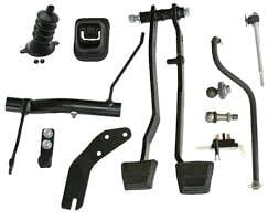
Looking for some help with a manual linkage/clutch pedal install in a 78 malibu originally equipped with a th350. I am using the clutch pedal/linkage kit similar to the OPG kit (see pic). I just need a little help getting started, installing the pedal and where the bracket goes on the frame, the z bar etc. Pics would be helpful! I have scoured the internet and have not been able to find much relevant info. It appears most are asking hydraulic retrofit oriented questions.

PS I have a T-10 I will be mating to a 350. I already have the attached kit (pic), the trans, g body bellhousing, clutch, flywheel etc, I should have just about everything and am ready to get started!
 

Attachments

  • 424ED647-3CDB-4DFA-949C-23415AD30D68.jpeg
    424ED647-3CDB-4DFA-949C-23415AD30D68.jpeg
    7 KB · Views: 170
Hey All,

Looking for some help with a manual linkage/clutch pedal install in a 78 malibu originally equipped with a th350. I am using the clutch pedal/linkage kit similar to the OPG kit (see pic). I just need a little help getting started, installing the pedal and where the bracket goes on the frame, the z bar etc. Pics would be helpful! I have scoured the internet and have not been able to find much relevant info. It appears most are asking hydraulic retrofit oriented questions.

PS I have a T-10 I will be mating to a 350. I already have the attached kit (pic), the trans, g body bellhousing, clutch, flywheel etc, I should have just about everything and am ready to get started!
The pedal install is a little bit of a pain. I put the same kit in my 82 El C when I put a Muncie in. The frame holes were there but needed to be tapped. Use fine thread bolts and lock tight. The block was drilled so it is a bolt up. There was a dimple on the fire wall as I recall for the clutch linkage. Hard to take pics as cramped area. All in all went pretty smooth. Driveshaft and crossmember worked.
 
  • Like
Reactions: Ugly1 and Baker7888
The pedal install is a little bit of a pain. I put the same kit in my 82 El C when I put a Muncie in. The frame holes were there but needed to be tapped. Use fine thread bolts and lock tight. The block was drilled so it is a bolt up. There was a dimple on the fire wall as I recall for the clutch linkage. Hard to take pics as cramped area. All in all went pretty smooth. Driveshaft and crossmember worked.
Thanks for the response! This is helpful. I heae ya on the cramped-ness. I did a T-5 swap in a 87 Camaro a few years back. It was all hydraulic so there were no linkages or brackets. The pedals came on a rack you just had to bolt up to the firewall. If anyone else has pics, of anything, let me know. It will help the process of elimination.
 
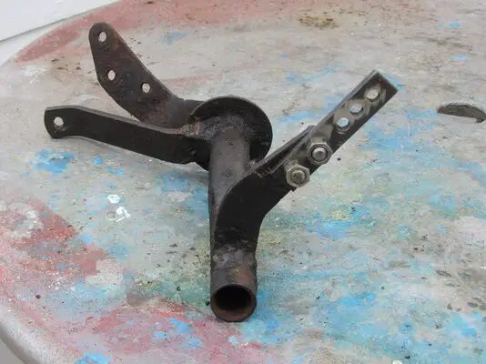
The whole brake pedal assembly has to come down. That means the power booster or master cylinder has to get unbolted too. Then you swap the clutch pedal assembly. Removing the steering column helps a lot. The bracket for the Z-bar bolts to the frame. Most frames are drilled for the bracket as the manual trans was standard on base cars. As Greg said, the ball stud goes on the block and again, was standard so the hole should be there. Make sure the machined block pad is totally flat so the stud sits flush. You may find the firewall hole is off a bit but the bellows will cover it. The Z-bar slips onto the ball stud then slides into the slot on the bracket. Grease the insides and make sure the felt washer is in there or it will leak out fast. Before you install it you may want to reinforce the Z-bar. They tend to break at the welds especially with a B&B type clutch. Here is a pic where I added a big washer and welded it to one arm and added more weld to the other arm. You must disassemble the entire Z-bar and clean the grease out to do it. IMG_1032.JPG
 
Last edited:
Thought I had some pictures of the conversion job from auto to manual that I did for my own Monte but apparently I never did generate a complete set of pics


DSCN2462.JPG


This is what I elected to do to brace the one arm on the Z-Bar. The actual brace is 1/8th x either 3/4 or 1 inch angle that I cut and shaped to match the od of the tube and the angle at which it butted up against the arm. Mig welded it all together and did some finishing to it for the pretty factor. The other end is done about the same way.

All my parts for this exercise were factory items that i had harvested from various hulks over a number of years. What that did was to give me an already assembled swing pedal set, several in fact, from which i could chose the best pieces and build what I wanted.

For my Monte, the holes in the frame for the bracket actually were already there, just covered over with a lot of paint and assorted crud. Cleaned them out and used a set of factory bolts for the install.

As pointed, the hole on the block ought to be there and tapped. Physically it is located just above the mount for the oil filter. Take a chasing tap and run it into the boss to clean it out before trying to run in the pivot ball. If the Z bar that you get comes to you with a plastic plug popped into a hole in the tube, pull the plug and install a grease fitting. That is the why of that hole and makes keeping the Z lubricated a whole lot easier that taking it apart to do it.

Don't see the two springs in the picture. You will need a clutch return spring and there is also one that rides along side the rod between the Z-bar and the throw out arm to keep the rod from popping out once it is adjusted. i can upload a picture of that if you think it might be useful.


DSCN2488.JPG


DSCN2487.JPG


DSCN2470.JPG


DSCN2472 (2).JPG


Just a couple of shots of the Z-Bar post modfication, showing the the bracing for each end. plus a some shots of the assembly as it is attached to the frame. You may have to tweak the path that your front brake line to the driver's side caliper uses or the Z and the line can seriiously rub on one another.

A note about Pic #4, The arm showing in that picture is the lower arm to which the rod for the throwout arm would be mounted. To get the alignment between the rod and the arms that i wanted, I had to both twist and bend the outer ear of that arm and what you see is the offset that I had to create to make me happy. For the welding aspect, I Vee-d both sides of the plate for each end of the joint and did the welds. They were deliberately left proud of the original surface to leave as much material as possible in the interest of strength. Did not see any point in pretty as you never see it most of the time and anyone wanting a closer look is going to have to imitate an earth worm to do it.


Nick
 
Last edited:
Screen Shot 2022-06-03 at 8.40.09 AM.png
 
The pedals ride on a common bolt. I was able to slide the short automatic pedal bolt out, then slide the longer manual bolt in, adding the two manual pedals, by only loosening the steering column bolts and letting it drop so I could get my hands up in there. Make sure you have the bushings (#13) and put a light smear of silicone lube on the bolt side. This stuff does not evaporate and get gummy like oil-based grease does.
 
Last edited:
Status
Not open for further replies.

GBodyForum is a participant in the Amazon Services LLC Associates Program, an affiliate advertising program designed to provide a means for sites to earn advertising fees by advertising and linking to amazon.com. Amazon, the Amazon logo, AmazonSupply, and the AmazonSupply logo are trademarks of Amazon.com, Inc. or its affiliates.

Please support GBodyForum Sponsors

Classic Truck Consoles Dixie Restoration Depot UMI Performance

Contact [email protected] for info on becoming a sponsor