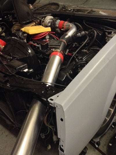
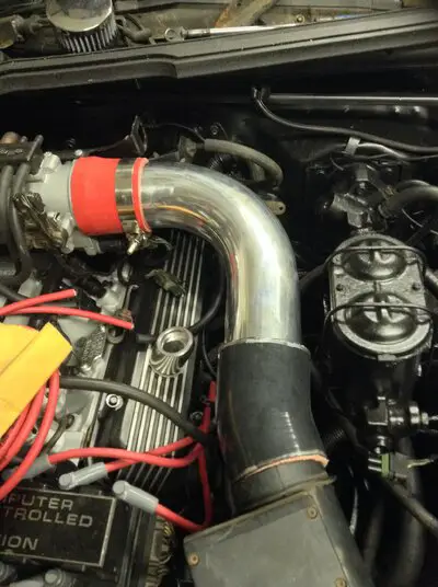
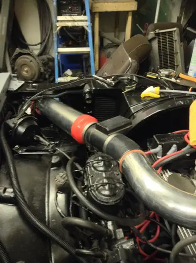
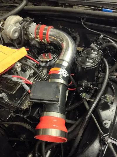
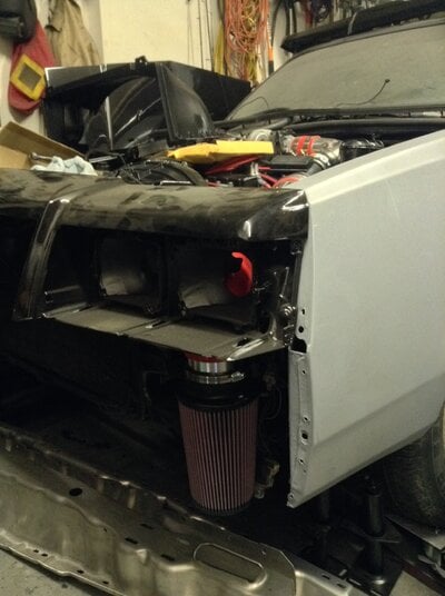
My own made 4" cold air intake
- Thread starter tobyp
- Start date
You are using an out of date browser. It may not display this or other websites correctly.
You should upgrade or use an alternative browser.
You should upgrade or use an alternative browser.
- Status
- Not open for further replies.
shows what you can do with a little creativity! 😛 if I hadn't gone cowl induction, this would've been a guide for me. love the placement!
Make sure the ID of the piping is the same as the MAF sensor or it will misread all the time.
If the MAF sensor housing inner diameter changes in any way, the calculation performed by the engine management system will be incorrect. This means that the amount of air actually entering the system will be different from what the computer thinks is entering the system. This is critical because the computer determines how much fuel and timing to run based on this value of air. When it's wrong, it can cause the engine to run richer, or leaner, than it should.
With aftermarket intakes, it's extraordinarily common for the piping used to have a different inner diameter than the MAF sensor housing incorporated in the factory air box. This is due to the fact that the exact inner diameter of the factory MAF sensor housing is different than what's commonly available in the standard metal piping used for aftermarket intake systems.
It is true that some aftermarket intakes show an increase in power when installed on a stock vehicle. This power increase is due to the fact that the aftermarket intakes have a larger inner diameter for the MAF sensor housing to mount into which in turn leans out the Air/Fuel mixture because of this error in calculating how much air is actually entering the system.
Please note this is NOT due to the fact that the aftermarket intake is so much less restrictive than the stock air box and therefore more air is getting in but rather that the computer does not know it's now sucking from a larger tube and therefore more air is getting in.
So to recap, whenever the MAF sensor housing size is increased compared to stock, more air will enter the system than the engine management has been calibrated for and you will run leaner. If the MAF sensor housing size is decreased compared to stock, less air will enter and you will run richer.
My kit uses stock maf and same diameter to throttle body after Maf. The difference is less restriction as well as airflow volune increasing before the maf and smooth flow after the maf. Also....cold air from completely outside the engine bay
It also needs to be the same ID before the MAF and the MAF sensor should not be right behind any bends, joints, welds, or even the air intake of filter. The air needs a chance to smooth out before flowing through the MAF to prevent misreadings. Unlike the errors created by the different size of piping, there are no corrections one can make for an intake design that allows turbulence across the MAF sensor. CAI designs where a MAF sensor are involved are very tricky, much more so than with a old carbed motor.
When dealing with the issue of a different MAF sensor housing inner diameter, the best solution is to simply recalibrate the factory engine computer for the new air flow. For those intakes that generate turbulence across the MAF sensor, there unfortunately is no easy solution. Since this turbulence can occur at different points in the power band, based on both engine RPM and engine load, all that can be done to make the engine run safely is to recalibrate the engine with a relatively rich overall tune. While this isn't the best for power, it will help protect the engine. This is with any engine that uses a MAF sensor. As vehicles get more complex, however, the once infallible upgrade path of replacing the factory intake air cleaner system needs to be reevaluated.
If you have a means to data log, I would watch the MAF readings to make sure there aren't any problems. Also I would rig up a splash shield just in case.
have scanmaster 2.1; Snapon ALDL diagnostic "brick" I can watch my 02 millivolts change from 300-700 and monitor air flow. The mass air sensor is making the appropriate readings in conjunction with the TPS .40 +/- .5, 02, ICA 10-20 steps to richen and lean out the mix. Keep in mind on this car,if you want to lean out on launch....decrease fuel pressure 1lb for 1lb of boost, for richen on launch do the opposite. Keep in mind, this is a turbo car, the more air, and the more in tune the person is with their car the better. Keeping the fine balance of 700 millivolts at launch and 398-402 at idle is sweet spot for tune and safety of the engine.
- Status
- Not open for further replies.
Similar threads
- Replies
- 10
- Views
- 551
- Replies
- 10
- Views
- 451
- Replies
- 8
- Views
- 477
- Replies
- 26
- Views
- 965
GBodyForum is a participant in the Amazon Services LLC Associates Program, an affiliate advertising program designed to provide a means for sites to earn advertising fees by advertising and linking to amazon.com. Amazon, the Amazon logo, AmazonSupply, and the AmazonSupply logo are trademarks of Amazon.com, Inc. or its affiliates.


 .lol good job though