Hello gentlemen, hope everyone is doing well. Got this project almost done finally! It actually runs and runs well after a few snags and issues that I had to deal with. Not unexpected, as I was sure I would be having some things that needed to be addressed upon Start up.
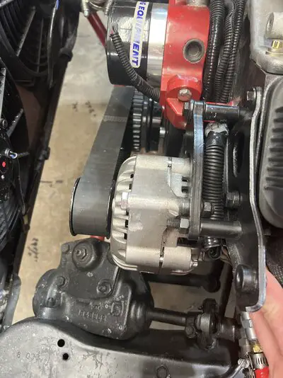
So, the final issue I’m having g is no charging voltage from the alternator.I originally had a serp belt set up from a blazer on this sbc, but after some design changes, and eliminating some things, I now have a Gilmer belt system, and only have the alternator driven by the belt.
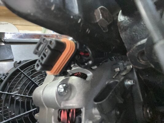
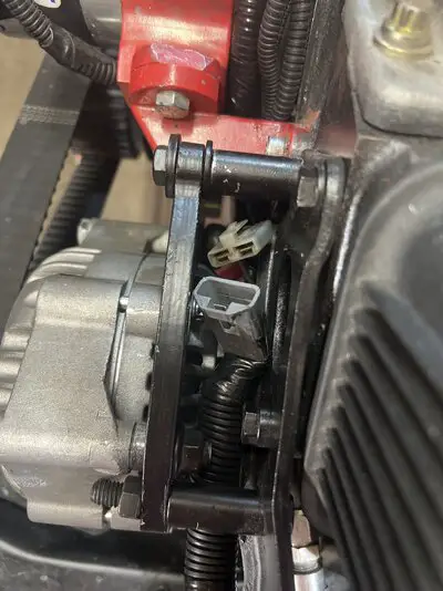
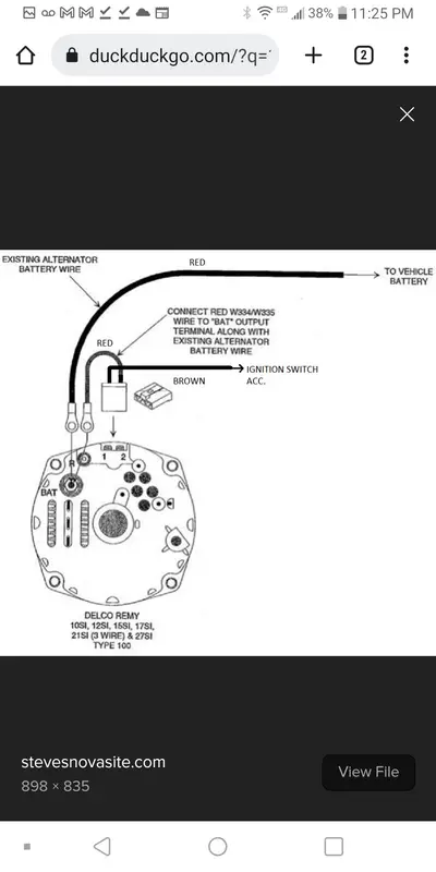
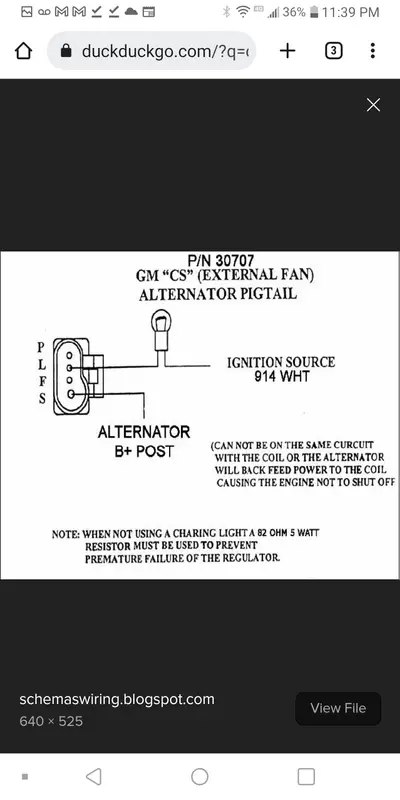
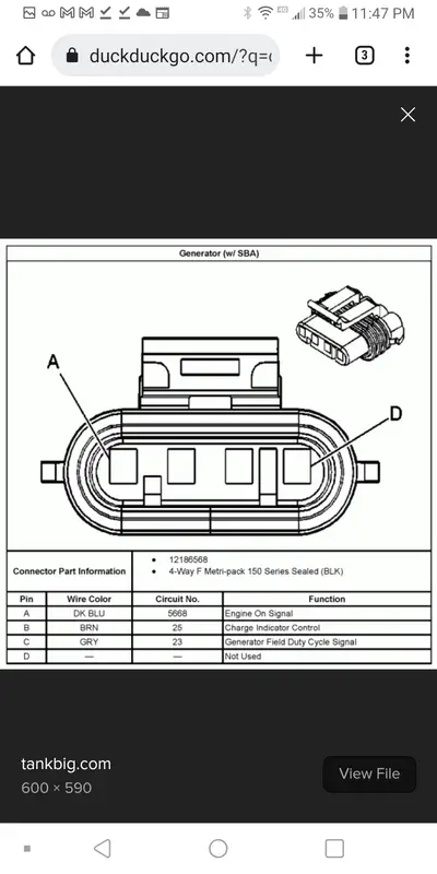
My question is, I have eliminated the OE dash, which had the warning lights, and installed an updated instrument cluster and printed circuit board with gauges. I did alter the wiring for the tach, and installed new sensors, but for the generator I did nothing to the OE wiring. I have the alternator mounted good and securely, and have installed an adaptor from the OE 10SI plug to the new CS130D alternator. It has 4 pins on rhe alternator, labeled PLIS, and it has a 500 ohm resistor in the proper wire.
From what I have researched, this should be the exciter wire, that supplies voltage to get the alternator charging. I do believe the OE wiring still has the original resistor in it as well.
Problems and questions are these:
I have no switched voltage to the alternator when I turn the ignition key on.
The resistance readings are approx 900 ohms when I measure from the fuse box inside the car to the plug for the alternator vs. 500 ohms when I measure from the alt plug to the wire just before it goes into the fuse box in the engine bay.
So………
A. Should I remove the resistor in the adaptor and just use the OE one, or eliminate the OE resistor in the original wiring and only use the one in the adaptor?
B: What pin should it be on? “L”or “I”? I have no light anymore, but I do still have the OE wiring FOR the light.
C: Why do I not have voltage on this wire when I turn the ignition key on? Should I not have voltage on this wire? Should I run a separate wire for the switched voltage supply and put it on the pin the the resistor wire is on or that it is not on?
Any advice is helpful as always guys! Thanks in advance for any responses.
Bill
Attachments
Last edited:


