

Forgot to add last night, when I took the carb off, seemingly many of the bolts had about 2 inch-pounds of torque on them. Took hardly anything to get them loose. Most all of them, yet the gasket witness marks seemed to be a good seal. That and the accelerator tube laying it its well were problems I wasn't able to readily see. Car didn't run bad, just didn't run as excellent as it used to. Now I think I know at least part of the reason why.
442 1985 442 Carburetor Stock Restoration-Refurbish
- Thread starter 69hurstolds
- Start date
You are using an out of date browser. It may not display this or other websites correctly.
You should upgrade or use an alternative browser.
You should upgrade or use an alternative browser.
Things always progress nicely when you don't need it or have to ensure something doesn't go wrong.
But when you really need things to go your way, the fight ensues. Yesterday was no exception.
I devised a method to access the idle mixture screws on the base plate while not having to chisel the bottom section away to get the plug out. These plugs are hardened steel and a real PITA to drill through. However, armed with a half-eaten Dremel cutoff wheel attached to the dremel, I cut an "x" into the end of the metal plug. These things have a slight domed top on them, and they're tough as nails, so just trying to drill through it would be a chore, even on a drill press. They really didn't want anyone getting to these bad dads. Once the mark was cut on the end, though, a small drill bit could eat its way through the cap top while the area with less meat now in the center, plus it kept the drill bit from walking. Popped through the dome, then used subsequently larger drill bits. There's quite a bit of space before you run into the screw. I was surprised. I stopped the enlargement when I got through with the 1/4" drill bit and then swapped back to the dremel with the cone grinder. I smoothed out the hole and enlarged it slightly so I could get to the screws easily. The barrel of the cap stays in, but the lid is gone and it doesn't look super horrible. Forgot to take pictures, but there's not much to show, actually. If I remember I'll take some.
All in all, it was a total PITA, but it netted me with access to the idle mixture screws with enough room to get the double D tool in there to turn them. Plus, I may be able to get little caps to put back over the holes and it won't look too damaged. Or dab a bit of silver gutter RTV across the top once everything is set and maybe it'll pass. I don't know yet. Blew carb cleaner spray into the hole to clean it out. The RH, passenger side screw came right out.
The LH, or driver side idle mixture screw was giving me fits. For whatever reason, it did NOT want to move more than a 1/2 turn either forward or back. I "rocked" the screw back and forth some, then proceeded to blow out the hole with more carb cleaner. Let it sit for a bit, more rocking. Better, but not much. Filled up the hole with Evaporust and let it sit for a few hours, then tried again. Better, but still not doing what I want. So I dragged out the PB Blaster and shot some into the hole filling it up, then sprayed it on the back side of the threads as well (small port on the top of the base you can just see the top of the screw where it starts to taper). Let it sit overnight.
Just got done with it. Rocked it some more and it moved quite a bit. Thought I was going to have to whip out the heat gun, but didn't have to. The screw finally came out without breaking anything, but there was quite a bit of rust on the upper threads. The screws are metric, M4 x 0.50 pitch. Super fine, but what's new. I don't have a tap that small and I can't find one locally today on Sunday. I have an M3 x 0.50, and an M4 x 0.70, so I had to order one from Amazon. Says it'll be here by tomorrow. No biggie, but for 10 bucks, it'll be good to have it and it comes with a matching die, so I can run the metering screws through it and clean up those threads. Chase those threads a bit and hopefully they'll be good to go. I'll put it in my carrying case with the rest of the carburetor tools.
Now the base is completely disassembled, along with the rest of the stuff. Tomorrow I think I'm going to sort through what's what, as far as what to replace, what to get replated, etc., etc., and pack it up and send it to the replating place.
I'll probably get some new brass screws from one of the quadrajet parts places to try and avoid the steel rust crap in the future, I dunno. I'm also going to do the mod on the end of the screws, whether or not I go new with the screws. We shall see. The mod entails simply using the dremel cutoff wheel and cutting a slot right in the middle of the mixture screw head. So then you can use a double D tool OR just a small flatblade screwdriver to turn the screws. More options. See pic below where green arrow is pointing. Yellow is where you would cut the slot.
I bought the longer slotted Metric screws from Cliff for my 83 non CCC carb, I rebuilt and retuned. Yeah, the brass screws would be way easier to slot than the hardened steel ones. Those plugs are a b*tch to remove. Most were removed years back, another sign for a non molested car. Cool thread BTW.
Things are progressing nicely. Keep looking over my shoulder waiting for the other shoe to drop. I disassembled the carburetor going out for plating as far down as I could get it. Now it's time to determine who should get my business. I've exchanged emails with a few folks who do this sort of thing, and Sparky's wasn't one of them. They seem rather adamant about not touching a CCC carb. For simple plating job, it's the same as far as I can tell. Whatevs. I've actually settled on a guy, but waiting to dole out the information until he's done and I've got my parts back. Then, good or bad, I'll tell you who got the job and my initial review of the work.
With finding a suitable bowl replacement for the damaged one, I was piddling around ebay looking at Q-jet parts, and ran across an airhorn that had a separate rich stop adjustment. It was a Chevy part number for a 305 Monte SS or F-body, 81-86. Meaning it was a 4-point adjustment system. The more I looked at it, the more it appeared it just might be able to made to work for a 3 point adjustment system. Decent price, I made an offer and was accepted, so now I have an NOS lid to go with the NOS float bowl.


Adjustable rich stop. Only found in 3 and 4 point adjustment carbs. In the pic, you can see the idle air bleed valve pintle right behind the rich stop.

Here's the thing about 4-point system vs. 3 point. They operate the same with the exception of the idle bleed valve has no letter stamped on top. In mid-year of 83, they brought out the 3-point adjustment on some cars, and you had a lean stop, rich stop, idle air bleed and idle mixture screw adjustments. Even the 3 point sort of uses 4 adjustments, but moreso depends on idle mixture screws vs. idle bleed valve. On the 4 point, you adjust the idle bleed valve, and if that changed dwell, then you jacked with the idle mixture screws, and go back and forth until you get your 25-35 degree dwell. So think of it like a 2-point system except you have a rich stop thrown in there. The pintle valve was revised on the "lettered" air bleed valves to restrict air bleed even moreso than the non-lettered bleed valves, so you set the lettered one with the measurement tool, and you SHOULDN'T have to mess with it again, and primarily use the idle mixture screws. If you don't look at the letter, you cannot tell the difference, though.
Now, what's different about the Chevy air horn and the Olds 442 air horn? A few things, and that's it. All can be "fixed" to use on a 442. I studied them side by side and compared everything I could think of. And here's what I found out...
What's different?
1. Tang on secondary air valve stop. Dremel cutoff wheel can care of that. (Olds airhorn on top, Chevy on bottom) Note on the Olds you can see where the 3/16" holes are for the idle bleed valve on the side of the vent tower. Chevy doesn't have the holes here, there are slots in the front that do the same thing. Never mind the blue tape. It's only there to hold the shafts in place so they don't fall out.

2. Idle air bleed has no letter. Swap it out with a lettered one. No big deal. The air portings go exactly where the other ones would go, so there's nothing to see here. BUT- looking carefully at the air idle bleed raised section, HOW the air gets into the valve is slightly different. The Olds uses two 3/16" holes on either side of the tower, just below the rivet holes where the little air bleed valve cover was riveted to. On the Chevy, there are slots cut in the front of either side of the tower facing forward. Basically taking in filtered air, just does it a bit differently. Note the air feed slots here. Without the cover, though, it doesn't matter where the holes are. There's plenty of filtered air to be had in that area.

3. Chevy does not use main well air bleed restrictors. Just an open hole. Olds has tiny little 1/8" diameter brass plugs with a 0.047" hole drilled into it. As luck would have it, the carcass body with the broken lean stop to the rescue. It has 1/8" cup restrictors with about a 0.30" hole in either side of the venturis. So I just drilled them out to .047" and then reached behind them with a pick and gently popped them out. Now all I have to do is press them into the Chevy air horn and...instant restrictors! 🙂


4. The Chevy carb is an E4ME. Not an E4MC. Meaning electric choke. Meaning it does not need the little air intake tube to the choke stove and tubing. Filtered air runs down into the rear channel of the carb and is drawn through the system into the choke housing. 1/4" hole in the back and a 1-1/8" length of tubing and boom. Fixed. Rubber hose adapter piece installs on the little bit of tubing hanging off the back and fits up that long, pricey tube to the choke stove. Olds on the left, Chevy on the right.

And that, my friends, is the ONLY differences I can find. Thus, there should be no problems doing the little mods to make it work on a 442.
And here's one of those "I never knew that" about E-jets. Ever notice that little hole underneath the curb idle adjust screw? I never paid much attention, but that tell-tale hole vents the well that the TPS sensor body rides in. So in the event you spring a gas leak around there, it drains away instead of shorting out your sensor and you should be able to tell.

With finding a suitable bowl replacement for the damaged one, I was piddling around ebay looking at Q-jet parts, and ran across an airhorn that had a separate rich stop adjustment. It was a Chevy part number for a 305 Monte SS or F-body, 81-86. Meaning it was a 4-point adjustment system. The more I looked at it, the more it appeared it just might be able to made to work for a 3 point adjustment system. Decent price, I made an offer and was accepted, so now I have an NOS lid to go with the NOS float bowl.
Adjustable rich stop. Only found in 3 and 4 point adjustment carbs. In the pic, you can see the idle air bleed valve pintle right behind the rich stop.
Here's the thing about 4-point system vs. 3 point. They operate the same with the exception of the idle bleed valve has no letter stamped on top. In mid-year of 83, they brought out the 3-point adjustment on some cars, and you had a lean stop, rich stop, idle air bleed and idle mixture screw adjustments. Even the 3 point sort of uses 4 adjustments, but moreso depends on idle mixture screws vs. idle bleed valve. On the 4 point, you adjust the idle bleed valve, and if that changed dwell, then you jacked with the idle mixture screws, and go back and forth until you get your 25-35 degree dwell. So think of it like a 2-point system except you have a rich stop thrown in there. The pintle valve was revised on the "lettered" air bleed valves to restrict air bleed even moreso than the non-lettered bleed valves, so you set the lettered one with the measurement tool, and you SHOULDN'T have to mess with it again, and primarily use the idle mixture screws. If you don't look at the letter, you cannot tell the difference, though.
Now, what's different about the Chevy air horn and the Olds 442 air horn? A few things, and that's it. All can be "fixed" to use on a 442. I studied them side by side and compared everything I could think of. And here's what I found out...
What's different?
1. Tang on secondary air valve stop. Dremel cutoff wheel can care of that. (Olds airhorn on top, Chevy on bottom) Note on the Olds you can see where the 3/16" holes are for the idle bleed valve on the side of the vent tower. Chevy doesn't have the holes here, there are slots in the front that do the same thing. Never mind the blue tape. It's only there to hold the shafts in place so they don't fall out.
2. Idle air bleed has no letter. Swap it out with a lettered one. No big deal. The air portings go exactly where the other ones would go, so there's nothing to see here. BUT- looking carefully at the air idle bleed raised section, HOW the air gets into the valve is slightly different. The Olds uses two 3/16" holes on either side of the tower, just below the rivet holes where the little air bleed valve cover was riveted to. On the Chevy, there are slots cut in the front of either side of the tower facing forward. Basically taking in filtered air, just does it a bit differently. Note the air feed slots here. Without the cover, though, it doesn't matter where the holes are. There's plenty of filtered air to be had in that area.
3. Chevy does not use main well air bleed restrictors. Just an open hole. Olds has tiny little 1/8" diameter brass plugs with a 0.047" hole drilled into it. As luck would have it, the carcass body with the broken lean stop to the rescue. It has 1/8" cup restrictors with about a 0.30" hole in either side of the venturis. So I just drilled them out to .047" and then reached behind them with a pick and gently popped them out. Now all I have to do is press them into the Chevy air horn and...instant restrictors! 🙂
4. The Chevy carb is an E4ME. Not an E4MC. Meaning electric choke. Meaning it does not need the little air intake tube to the choke stove and tubing. Filtered air runs down into the rear channel of the carb and is drawn through the system into the choke housing. 1/4" hole in the back and a 1-1/8" length of tubing and boom. Fixed. Rubber hose adapter piece installs on the little bit of tubing hanging off the back and fits up that long, pricey tube to the choke stove. Olds on the left, Chevy on the right.
And that, my friends, is the ONLY differences I can find. Thus, there should be no problems doing the little mods to make it work on a 442.
And here's one of those "I never knew that" about E-jets. Ever notice that little hole underneath the curb idle adjust screw? I never paid much attention, but that tell-tale hole vents the well that the TPS sensor body rides in. So in the event you spring a gas leak around there, it drains away instead of shorting out your sensor and you should be able to tell.
I have already sent my disassembled original carburetor off to the plater services to get replated, and it has a fairly decent journey to go. Shipping 11 lbs of aluminum and steel bits gets kinda pricey pretty quick nowadays ($37). Anyway, it's scheduled to arrive at the plater's Tuesday, so we'll see what they have to say/do and figure on a couple of weeks turnaround on it (have no idea how long it will take) I got some down time on this.
I was kinda surprised to learn that mixture control solenoids (MCS) aren't readily available any longer, and when they are found, they're EXPENSIVE. Like around $80- $100 a pop. I'm glad I stocked up when I did. I got a handful of new ones, but I have a slightly used MCS I've been keeping around so maybe I can use it in my "Chev-Y 442" carburetor. According to the CSM troubleshooting chart, the resistance check for the MCS is performed it must be above 10 ohms, or it will need replacing. Be aware that if it comes in at say, 7 ohms or thereabouts, the MCS can still click when in closed loop, but may NOT operate correctly causing all sorts of drivability issues. According to GM, >10 ohms and it's considered good. Piddling around on the interwebs, I've noticed that a "internet normal" anecdotal reading is around 25 ohms for a known, operating MCS, plus or minus a few ohms.
For my little meter, a Fluke T5-600, if you have a short, you will see a 0 on the screen. This is usually a very bad sign and likely results in replacement if you're not good at fixing solenoids.
If you have an open line, showing "OL" (or infinity symbol on other brands), likely the solenoid wiring has a break in it. If you're lucky, the break will be in the little external wires and you can fix it. If it's inside the unit, unless you know how to do electronics, you'll likely have to replace.
Here's one of my used ones getting a resistance check. I'm probably going to use this one for the Chev-Y 442 carb. I am going to use a brand new Delco unit for the restoration unit when I get it back. Probably a good idea to resistance check ALL MCS whether new or not. Takes just a few seconds to do, and may save you problems later. As you can see, it comes in at 25 ohms. For reference, I checked a brand new one and it came in at 24 ohms. I'm going to call it good.

EDIT: I forgot to add ONE extra check on the MC Solenoid. New or used going back in the carb, you might want to check your MC Solenoid for any "opens" between the terminals. How you would do that is get your ohm meter out and check each terminal for the MC Solenoid plug against the metal housing of the solenoid. You should get an "Open" reading, or "Open Line" or "OL". Basically, you should get no reading. If you get a direct short, this means your solenoid isn't going to work and you'll need to fix yours or get another one. Easy to do, takes about 3 seconds to complete the whole check. First terminal shows OL. Good deal.

And now the other terminal...OL...means it's not shorted! Good.

I was kinda surprised to learn that mixture control solenoids (MCS) aren't readily available any longer, and when they are found, they're EXPENSIVE. Like around $80- $100 a pop. I'm glad I stocked up when I did. I got a handful of new ones, but I have a slightly used MCS I've been keeping around so maybe I can use it in my "Chev-Y 442" carburetor. According to the CSM troubleshooting chart, the resistance check for the MCS is performed it must be above 10 ohms, or it will need replacing. Be aware that if it comes in at say, 7 ohms or thereabouts, the MCS can still click when in closed loop, but may NOT operate correctly causing all sorts of drivability issues. According to GM, >10 ohms and it's considered good. Piddling around on the interwebs, I've noticed that a "internet normal" anecdotal reading is around 25 ohms for a known, operating MCS, plus or minus a few ohms.
For my little meter, a Fluke T5-600, if you have a short, you will see a 0 on the screen. This is usually a very bad sign and likely results in replacement if you're not good at fixing solenoids.
If you have an open line, showing "OL" (or infinity symbol on other brands), likely the solenoid wiring has a break in it. If you're lucky, the break will be in the little external wires and you can fix it. If it's inside the unit, unless you know how to do electronics, you'll likely have to replace.
Here's one of my used ones getting a resistance check. I'm probably going to use this one for the Chev-Y 442 carb. I am going to use a brand new Delco unit for the restoration unit when I get it back. Probably a good idea to resistance check ALL MCS whether new or not. Takes just a few seconds to do, and may save you problems later. As you can see, it comes in at 25 ohms. For reference, I checked a brand new one and it came in at 24 ohms. I'm going to call it good.
EDIT: I forgot to add ONE extra check on the MC Solenoid. New or used going back in the carb, you might want to check your MC Solenoid for any "opens" between the terminals. How you would do that is get your ohm meter out and check each terminal for the MC Solenoid plug against the metal housing of the solenoid. You should get an "Open" reading, or "Open Line" or "OL". Basically, you should get no reading. If you get a direct short, this means your solenoid isn't going to work and you'll need to fix yours or get another one. Easy to do, takes about 3 seconds to complete the whole check. First terminal shows OL. Good deal.
And now the other terminal...OL...means it's not shorted! Good.
Last edited:
While I'm waiting for the plater to get done, figured I may show how to do a resistance check on a TPS. Just like thermostats, it's a good idea to test them before you install them to ensure they are working correctly or as expected before just tossing them in and buttoning them up. Bad ones from the factory do happen sometimes. No sense doing the work twice.
The CSM calls out for doing an ohm check on a TPS sensor specifically when you have a high voltage from your TPS throwing a CEL code 22. In it, there is a troubleshooting step to perform an ohm test. Your result needs to be <20K ohms or they consider the TPS bad and you should replace it. Test across the A to B and A to C terminals on the TPS sensor. Which one is which???
ABC goes from top to bottom. Or as you're holding it in your hand, how it would mount in the carburetor with the catch tab for the plug tang on the inside toward the fuel inlet nut and the moveable plunger would be facing up. A terminal is your 5V reference voltage from the ECM, the B terminal is your regulated/measured voltage based on throttle position, thus plunger position, and C is your common, or ground.
With this info in hand, it's pretty easy to do.
Note we're on the 20K ohm scale, terminals A-C. Thus, the 15.10 is actually 15,100 ohms. Less than 20K per GM, therefore- GOOD.

Now we check the A to B with plunger fully extended (idle). Should expect it to be high.
And it is. The reading is 16.07, which equates to 16,070 ohms. Still under 20K ohms. Per GM- Call on the field still stands. GOOD!

I wasn't going to do any movie clip or anything, but at this point, you can gently press down the plunger on the TPS slowly and smoothly. Feel for any dragging, and watch for any jump or weird readings. Do it several times to get the feel for it and watch the readout. What you're looking for is smooth travel, and a relatively smooth and steady movement in ohm reading. I'm using a dirt cheap digital meter that fits in my carb tool box, so that's what I use for testing TPS resistance. Point is, it just needs to be <20K ohms and not have any noticeable skipping in the readings.
With plunger depressed fully, I get a reading of 920 ohms. Don't expect it to go to full short, but this TPS seems to operate just fine. This is only a bench test to ensure the TPS can be adjusted on the car and that you won't be crying later after putting it in and finding out it doesn't work. If it passes this test, you should be able to dial in your voltages on the car. Only takes a minute to do but is well worth the trouble. Good luck.

An additional note on why I like to use ACDelco sensors and such when working on G-body emission cars. Other than they're designed for the duty that they're going to see, as well as their proven track record of good reliability, they also come with stuff you may find you need that IS NOT SERVICED by GM then or now. Like the cool thing about an ACDelco TPS (17078448) is that you get everything you need to replace the TPS sensor. You get the spring, you get the plug, a cotter key (when they had issues with the roll pin working out on accelerator levers) and you get the NOT SERVICED green teflon coated TPS plunger piece that the accelerator lever contacts. If you've ever lost one of those little bits of gold, you'll be glad to get the ACDelco TPS kits.


The CSM calls out for doing an ohm check on a TPS sensor specifically when you have a high voltage from your TPS throwing a CEL code 22. In it, there is a troubleshooting step to perform an ohm test. Your result needs to be <20K ohms or they consider the TPS bad and you should replace it. Test across the A to B and A to C terminals on the TPS sensor. Which one is which???
ABC goes from top to bottom. Or as you're holding it in your hand, how it would mount in the carburetor with the catch tab for the plug tang on the inside toward the fuel inlet nut and the moveable plunger would be facing up. A terminal is your 5V reference voltage from the ECM, the B terminal is your regulated/measured voltage based on throttle position, thus plunger position, and C is your common, or ground.
With this info in hand, it's pretty easy to do.
Note we're on the 20K ohm scale, terminals A-C. Thus, the 15.10 is actually 15,100 ohms. Less than 20K per GM, therefore- GOOD.
Now we check the A to B with plunger fully extended (idle). Should expect it to be high.
And it is. The reading is 16.07, which equates to 16,070 ohms. Still under 20K ohms. Per GM- Call on the field still stands. GOOD!
I wasn't going to do any movie clip or anything, but at this point, you can gently press down the plunger on the TPS slowly and smoothly. Feel for any dragging, and watch for any jump or weird readings. Do it several times to get the feel for it and watch the readout. What you're looking for is smooth travel, and a relatively smooth and steady movement in ohm reading. I'm using a dirt cheap digital meter that fits in my carb tool box, so that's what I use for testing TPS resistance. Point is, it just needs to be <20K ohms and not have any noticeable skipping in the readings.
With plunger depressed fully, I get a reading of 920 ohms. Don't expect it to go to full short, but this TPS seems to operate just fine. This is only a bench test to ensure the TPS can be adjusted on the car and that you won't be crying later after putting it in and finding out it doesn't work. If it passes this test, you should be able to dial in your voltages on the car. Only takes a minute to do but is well worth the trouble. Good luck.
An additional note on why I like to use ACDelco sensors and such when working on G-body emission cars. Other than they're designed for the duty that they're going to see, as well as their proven track record of good reliability, they also come with stuff you may find you need that IS NOT SERVICED by GM then or now. Like the cool thing about an ACDelco TPS (17078448) is that you get everything you need to replace the TPS sensor. You get the spring, you get the plug, a cotter key (when they had issues with the roll pin working out on accelerator levers) and you get the NOT SERVICED green teflon coated TPS plunger piece that the accelerator lever contacts. If you've ever lost one of those little bits of gold, you'll be glad to get the ACDelco TPS kits.
Still waiting for my carburetor to get back from the plater's. Driving home from the grocery store today, it occurred to me that I couldn't remember how the rear vacuum break (RVB) aka, secondary vacuum break, solenoid was energized during start up. Also, how many people really don't understand how the Quadrajet choke system works. I mean, really works. What does what and when type of things. I truly believe that most carburetor issues are misadjusted linkages and lack of ANY type of maintenance on the carb.
So...breaking out the overhead projector again, lets go over a few things on a G-body Oldsmobile E4MC Quadrajet choke system. Again, this may be old hat to some of y'all who's messed with these carbs, or it could be brand new info for you. Maybe someone could learn a little about it and quit ripping the carburetors off along with the CCC system at the first sign of trouble.
Let's start off with the basic setup of the E4MC Olds Quadrajet choke system. Once again, I stress I am not an expert, but I do understand the functionality of most of the carburetor and supporting cast.
For the most part, all 80s G-body E4MC Quadrajets tend to have 4 main pieces to the choke system, besides the all important choke butterfly itself.
Those pieces are:
Primary choke pulloff
Choke housing/spring/fast idle cam assembly
Rear Vacuum Break, aka Secondary choke pulloff
RVB solenoid controlled from the ECM (not shown)
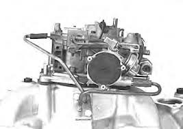
Here's a typical E4MC Oldsmobile style Quadrajet. Not all carburetors have a rear vacuum break, but most Oldsmobiles do. Pretty sure all the 307s do.
Red arrow- Primary Choke pulloff
Yellow arrow- Choke housing with main spring
Blue arrow- Rear Vacuum Break

Let's go over the choke housing first. This is where the main party takes place during the choke operation when the engine is cold. Note the black circle that's held on with phillips head screws (factory used rivets). It is attached to a bi-metallic coil spring that when cold, wraps itself up tight and attempts to close the choke butterfly via the linkage. After shutting off the car when warm, the choke spring is loose, allowing the choke butterfly to stay open, and your fast idle cam isn't even playing in the sandbox at this point as it's on the low step. So your curb idle screw is the only thing in play at this point (on driver side of carb). When the engine/carb cools off, the choke spring tries to close the choke, but it won't because of the fast idle adjustment screw keeps it on the low step on the fast idle cam. The choke needs to be set the next time you start the car when it's cold. This is done by pressing the gas pedal ONCE. When the primary throttle blades open, the fast idle cam adjustment step is pulled away from the choke linkage allowing the fast idle link/weight to release. This allows the choke spring to wind up and close the choke. This gas pedal action also squirts fuel into the intake via the accelerator pump shot.
Once the engine starts, filtered air is pulled through the back of the carbuetor air horn through the 1/4" tube. It connects to a heat stove (u-tube arrangement bolted to the intake into the cross-over port). Heated air is pulled from the heat stove tube into the choke spring housing. A small hole in the choke housing is routed to the intake via the main body of the carb. This way, hot air is pulled through the choke spring housing as long as the engine is running, keeping the spring loose allowing the choke butterfly to open, then stay open once the spring is hot.
This isn't an Olds hot air choke setup, but it's similar and works the same. I'm just using it as an illustration about how it needs the tubing to work. A note about the choke disc- early Quadrajets used an adjustable spring, while the E4MC used on the 307s had a fixed position. There's a notch in the black plastic disc that fits into a lug in the choke housing. Only one way to place it.
So that takes care of the choke housing. Most Chevies used an E4ME carb. Pretty much the same, but with an electronic choke. It didn't need the hot air tubes. Just a 12V source that when the ignition is on, the choke starts to heat up. That said, almost any hot air choke can be modified to be an electric choke, but obviously you need to block off the vacuum port in the choke housing to the carb, otherwise you'd have a useless vacuum leak.
Now on to the primary choke pulloff. Nobody ever thinks about this thing much until the diaphragm blows. More on that in a minute. First, let's take a couple of steps back to the point where you pressed the gas pedal once to set the choke and squirt some fuel into the intake. Now, the engine is cranked at this point, and assuming the rest of the engine components and systems are in working order, the engine reaches about 200 rpm and starts pulling more fuel from the carb into the intake. Choke is closed, so it will try and suck the eyes out of a parrot at this point and pull whatever it can from wherever it can. So if it can't suck air, it's going to suck gas. So now you have a super-rich environment as the engine is cranking, and that should give you enough fuel to vaporize and ignite in the combustion chamber, starting the engine. Vrroom! The engine comes to life!
You're now on the fast idle cam step keeping rpm up, and the engine is going to want some air to keep running. So what happens? The primary choke pulloff almost instantly reacts to the increased vacuum signal, and draws in the diaphragm, moving the extension rod toward the front. An adjustable actuator on the extension rod pulls forward, touching the choke linkage in a manner which opens the choke butterfly slightly as the engine starts allowing some air to help lean out the mixture into the engine and keep the engine running. This is an important aspect of the primary pulloff, because if the diaphragm is damaged, or the hose splits, the pulloff is inoperable, and will NOT open the choke butterfly at all. This will be exhibited by a super-rich conditions where once the engine starts, it will belch black smoke out the exhaust and stumble and most likely die quickly because it isn't getting any air. Super simple to change out if yours breaks, but also super simple to check with a mity vac or other vacuum tool. As with all pulloff diaphragm pods like this, vacuum applied should hold for 20 seconds, or the pod needs to be replaced.
Note on this carb, it also has a secondary link going to the secondary air valve. Wait, this is a PRIMARY pulloff, wtf? Yep, when the engine is running with high vacuum, the link rod is pulled to the front of the slot on the secondary air valves keeping them from opening, which would not be good for your engine. Once you get ready to go and the choke is off, once you floor it, the engine vacuum drops and the primary pulloff loses vacuum and returns to its idle state, which allows a more controlled opening of the secondaries. You don't have the air valves just flapping open immediately all at once.
A note on primary and secondary pulloffs. On this particular carburetor, the pulloffs do not have a bleed hole in them, nor are they readily adjustable. Some are, but in this case, no. So when testing ones that have a bleed hole, you'll need to tape the hole first. Just throwing that out there.
Now, on to the last thing, and that's the rear vacuum break. Has NOTHING to do with the secondaries at all. This one is a bit tough to explain on paper. Its vacuum signal is ECM controlled, via the RVB solenoid, which on the 5.0L Olds V8s is on the driver side rear of the engine. The vacuum signal comes from the small port on the back of the carb via about 40 feet of spaghetti vacuum hose, and under certain cold conditions, will open the choke butterfly slightly wider than the primary choke pulloff. This is a bit tougher to explain, because the RVB solenoid is normally de-energized allowing vacuum to pass through it. However, when the engine starts, the ECM sends a signal to energize the RVB solenoid effectively keeping it from operating for the first 30 seconds. By this time, if the engine is running right and it isn't 150 degrees below zero, the choke spring will start to loosen and open the choke more in that 30 seconds. If it's TOO cold out, the spring will still be tighter, the choke is still not opening as quickly. Once the 30 seconds is up, the ECM de-energizes the RVB solenoid allowing vacuum to pull the actuating rod connected to the choke butterfly linkage to open it slightly more than the primary pulloff would to help with atomization at the lower temperatures. Again, if the choke is already open to this point, the RVB operates like it's supposed to, but doesn't do anything.

There are people out there saying that the RVB is totally useless anyway, and you don't need it. Most of the time it's likely true. If you live in, say, Houston, or L.A., you probably won't get it cold enough to need the RVB. But in Manitoba during the cold winter, you just might. It doesn't hurt to have it, but if it doesn't work and you're in a warm climate, well, it likely won't be missed. But you do you. All I'm saying here is that now you know what it's supposed to do, and hopefully not just dismiss it out of hand.
When I go through the carburetor, I'll show you how all this junk gets adjusted. You'd be surprised how out of whack these things can be.
Hope I didn't leave anything out. If you got any questions, feel free to ask. I'll do what I can. Again, I'm not an expert. Cliff Ruggles is an expert.
So...breaking out the overhead projector again, lets go over a few things on a G-body Oldsmobile E4MC Quadrajet choke system. Again, this may be old hat to some of y'all who's messed with these carbs, or it could be brand new info for you. Maybe someone could learn a little about it and quit ripping the carburetors off along with the CCC system at the first sign of trouble.
Let's start off with the basic setup of the E4MC Olds Quadrajet choke system. Once again, I stress I am not an expert, but I do understand the functionality of most of the carburetor and supporting cast.
For the most part, all 80s G-body E4MC Quadrajets tend to have 4 main pieces to the choke system, besides the all important choke butterfly itself.
Those pieces are:
Primary choke pulloff
Choke housing/spring/fast idle cam assembly
Rear Vacuum Break, aka Secondary choke pulloff
RVB solenoid controlled from the ECM (not shown)
Here's a typical E4MC Oldsmobile style Quadrajet. Not all carburetors have a rear vacuum break, but most Oldsmobiles do. Pretty sure all the 307s do.
Red arrow- Primary Choke pulloff
Yellow arrow- Choke housing with main spring
Blue arrow- Rear Vacuum Break
Let's go over the choke housing first. This is where the main party takes place during the choke operation when the engine is cold. Note the black circle that's held on with phillips head screws (factory used rivets). It is attached to a bi-metallic coil spring that when cold, wraps itself up tight and attempts to close the choke butterfly via the linkage. After shutting off the car when warm, the choke spring is loose, allowing the choke butterfly to stay open, and your fast idle cam isn't even playing in the sandbox at this point as it's on the low step. So your curb idle screw is the only thing in play at this point (on driver side of carb). When the engine/carb cools off, the choke spring tries to close the choke, but it won't because of the fast idle adjustment screw keeps it on the low step on the fast idle cam. The choke needs to be set the next time you start the car when it's cold. This is done by pressing the gas pedal ONCE. When the primary throttle blades open, the fast idle cam adjustment step is pulled away from the choke linkage allowing the fast idle link/weight to release. This allows the choke spring to wind up and close the choke. This gas pedal action also squirts fuel into the intake via the accelerator pump shot.
Once the engine starts, filtered air is pulled through the back of the carbuetor air horn through the 1/4" tube. It connects to a heat stove (u-tube arrangement bolted to the intake into the cross-over port). Heated air is pulled from the heat stove tube into the choke spring housing. A small hole in the choke housing is routed to the intake via the main body of the carb. This way, hot air is pulled through the choke spring housing as long as the engine is running, keeping the spring loose allowing the choke butterfly to open, then stay open once the spring is hot.
This isn't an Olds hot air choke setup, but it's similar and works the same. I'm just using it as an illustration about how it needs the tubing to work. A note about the choke disc- early Quadrajets used an adjustable spring, while the E4MC used on the 307s had a fixed position. There's a notch in the black plastic disc that fits into a lug in the choke housing. Only one way to place it.
So that takes care of the choke housing. Most Chevies used an E4ME carb. Pretty much the same, but with an electronic choke. It didn't need the hot air tubes. Just a 12V source that when the ignition is on, the choke starts to heat up. That said, almost any hot air choke can be modified to be an electric choke, but obviously you need to block off the vacuum port in the choke housing to the carb, otherwise you'd have a useless vacuum leak.
Now on to the primary choke pulloff. Nobody ever thinks about this thing much until the diaphragm blows. More on that in a minute. First, let's take a couple of steps back to the point where you pressed the gas pedal once to set the choke and squirt some fuel into the intake. Now, the engine is cranked at this point, and assuming the rest of the engine components and systems are in working order, the engine reaches about 200 rpm and starts pulling more fuel from the carb into the intake. Choke is closed, so it will try and suck the eyes out of a parrot at this point and pull whatever it can from wherever it can. So if it can't suck air, it's going to suck gas. So now you have a super-rich environment as the engine is cranking, and that should give you enough fuel to vaporize and ignite in the combustion chamber, starting the engine. Vrroom! The engine comes to life!
You're now on the fast idle cam step keeping rpm up, and the engine is going to want some air to keep running. So what happens? The primary choke pulloff almost instantly reacts to the increased vacuum signal, and draws in the diaphragm, moving the extension rod toward the front. An adjustable actuator on the extension rod pulls forward, touching the choke linkage in a manner which opens the choke butterfly slightly as the engine starts allowing some air to help lean out the mixture into the engine and keep the engine running. This is an important aspect of the primary pulloff, because if the diaphragm is damaged, or the hose splits, the pulloff is inoperable, and will NOT open the choke butterfly at all. This will be exhibited by a super-rich conditions where once the engine starts, it will belch black smoke out the exhaust and stumble and most likely die quickly because it isn't getting any air. Super simple to change out if yours breaks, but also super simple to check with a mity vac or other vacuum tool. As with all pulloff diaphragm pods like this, vacuum applied should hold for 20 seconds, or the pod needs to be replaced.
Note on this carb, it also has a secondary link going to the secondary air valve. Wait, this is a PRIMARY pulloff, wtf? Yep, when the engine is running with high vacuum, the link rod is pulled to the front of the slot on the secondary air valves keeping them from opening, which would not be good for your engine. Once you get ready to go and the choke is off, once you floor it, the engine vacuum drops and the primary pulloff loses vacuum and returns to its idle state, which allows a more controlled opening of the secondaries. You don't have the air valves just flapping open immediately all at once.
A note on primary and secondary pulloffs. On this particular carburetor, the pulloffs do not have a bleed hole in them, nor are they readily adjustable. Some are, but in this case, no. So when testing ones that have a bleed hole, you'll need to tape the hole first. Just throwing that out there.
Now, on to the last thing, and that's the rear vacuum break. Has NOTHING to do with the secondaries at all. This one is a bit tough to explain on paper. Its vacuum signal is ECM controlled, via the RVB solenoid, which on the 5.0L Olds V8s is on the driver side rear of the engine. The vacuum signal comes from the small port on the back of the carb via about 40 feet of spaghetti vacuum hose, and under certain cold conditions, will open the choke butterfly slightly wider than the primary choke pulloff. This is a bit tougher to explain, because the RVB solenoid is normally de-energized allowing vacuum to pass through it. However, when the engine starts, the ECM sends a signal to energize the RVB solenoid effectively keeping it from operating for the first 30 seconds. By this time, if the engine is running right and it isn't 150 degrees below zero, the choke spring will start to loosen and open the choke more in that 30 seconds. If it's TOO cold out, the spring will still be tighter, the choke is still not opening as quickly. Once the 30 seconds is up, the ECM de-energizes the RVB solenoid allowing vacuum to pull the actuating rod connected to the choke butterfly linkage to open it slightly more than the primary pulloff would to help with atomization at the lower temperatures. Again, if the choke is already open to this point, the RVB operates like it's supposed to, but doesn't do anything.
There are people out there saying that the RVB is totally useless anyway, and you don't need it. Most of the time it's likely true. If you live in, say, Houston, or L.A., you probably won't get it cold enough to need the RVB. But in Manitoba during the cold winter, you just might. It doesn't hurt to have it, but if it doesn't work and you're in a warm climate, well, it likely won't be missed. But you do you. All I'm saying here is that now you know what it's supposed to do, and hopefully not just dismiss it out of hand.
When I go through the carburetor, I'll show you how all this junk gets adjusted. You'd be surprised how out of whack these things can be.
Hope I didn't leave anything out. If you got any questions, feel free to ask. I'll do what I can. Again, I'm not an expert. Cliff Ruggles is an expert.
Got word back from the plater today that he's getting through his backlog and I should be fixed up sometime next week. It's my TPW (target production week) I suppose. 🙂
Figure a few days for shipping, so my ballpark estimate is that I can get back on this project full steam right about the end of the month. So stay tuned for some updates as soon as I can get them.
Figure a few days for shipping, so my ballpark estimate is that I can get back on this project full steam right about the end of the month. So stay tuned for some updates as soon as I can get them.
Update: The plater has completed my project (he's got a healthy backlog), has been paid for his services, and will be sending back my freshly restored pieces/parts today or tomorrow. Fingers crossed that UPS or FedEx or whoever doesn't lose it. This means I'm guessing I should have the parts in hand sometime shortly after the 4th of July since it's a holiday weekend. Then the rebuild will commence. So roughly a total of 6 week turnaround since I sent it off until its return.
I had him check the need for shaft bushings and the primaries were needed, but the secondaries will remain original. Which is typical since spring pressures and such wreak havoc on the primary driver side bore especially. I could have done the bushing job myself, but since he was right there and offers the service, meaning I don't have to buy a reamer, bushings, or risk fugging it up, why not? He's got major experience with the procedure and I don't, so it was worth it to me.
I had him check the need for shaft bushings and the primaries were needed, but the secondaries will remain original. Which is typical since spring pressures and such wreak havoc on the primary driver side bore especially. I could have done the bushing job myself, but since he was right there and offers the service, meaning I don't have to buy a reamer, bushings, or risk fugging it up, why not? He's got major experience with the procedure and I don't, so it was worth it to me.
Similar threads
- Replies
- 3
- Views
- 312

- Replies
- 21
- Views
- 3K
- Replies
- 2
- Views
- 98
- Replies
- 1
- Views
- 150
GBodyForum is a participant in the Amazon Services LLC Associates Program, an affiliate advertising program designed to provide a means for sites to earn advertising fees by advertising and linking to amazon.com. Amazon, the Amazon logo, AmazonSupply, and the AmazonSupply logo are trademarks of Amazon.com, Inc. or its affiliates.