L31 into an '86 Regal Limited V8

Status
Not open for further replies.
ATL Regal said:
What wires I need to go in the firewall?

Keyed (switched) ignition
Constant power
Tach
Earl pressure
Water temp
VSS (from 4L60E)

I am using the L31 as a supplement to my existing harness, so I will try to answer the way I am doing it and maybe give you an option.
Keyed ignition- yes, hot in start and run position; I will use this signal to pick up a relay for the ECM and to pick up the fuel pump relay. The keyed ignition signal I will use is from the Nova harness wire to the coil (I think it is the only wire in the original harness that is hot in start and run).
Constant power-yes you will need +12V from the battery, you can pick this up anywhere with appropriate wire sizing, does not have to be from inside the car; note, you will probably need a fusible link between the supply and the ECM; check the GM drawing for appropriate sizing
Tach- yes, you need a tach signal; I have an aftermarket tach so I will add it to the harness per the manufacturer instructions
Oil pressure- yes, you will need oil pressure; again I have an aftermarket gauge and sender
Water temp- same
VSS- yes, for electric speedo


You will also need:
check engine light- this is labeled MIL; the PCM gives you the ground, the light in the car needs a 12V supply
serial communication- this is for the OBDII diagnostic, find wiring diagram for OBDII connector (I think there is +12 V ignition or batt, and grounds)
brake pedal signal- you will need a signal that the brake pedal is being applied to the PCM to disengage the TCC; you can do this with a cruise type brake switch (the signal is normally hot and broken when the pedal is depressed)
transmission controls- there are some wires to indicate which gear you have selected and a neutral safety switch to ensure the car won't start when you are in gear. I need to look at this closer. I have an aftermarket shifter and will have to integrate that.
AC wires- I removed all the wires for AC from the harness, I have an aftermarket Vintage Air system and will wiring it per their instructions.
Cruise Control- I will use the Suburban cruise control and thus the wires for that will go through the firewall

I have a 98 engine and harness. I will go through the PCM pin-out and mark each whether I kept it or deleted it and will be better prepared to answer your questions.

Mike
 
I was looking at the info on lt1swap.com last night and he has it laid out pretty well what is required: http://lt1swap.com/1999_vortec_5.7/index.htm

For the external connection, he tells you where it is on the existing connector, the color wire, and the electrical protection requirements.

I still need to look at the automatic transmission controls on connector 200 (engine harness to passenger harness).

Mike
 
nova_rookie said:
ATL Regal said:
What wires I need to go in the firewall?

Keyed (switched) ignition
Constant power
Tach
Earl pressure
Water temp
VSS (from 4L60E)

I am using the L31 as a supplement to my existing harness, so I will try to answer the way I am doing it and maybe give you an option.
Keyed ignition- yes, hot in start and run position; I will use this signal to pick up a relay for the ECM and to pick up the fuel pump relay. The keyed ignition signal I will use is from the Nova harness wire to the coil (I think it is the only wire in the original harness that is hot in start and run).
Constant power-yes you will need +12V from the battery, you can pick this up anywhere with appropriate wire sizing, does not have to be from inside the car; note, you will probably need a fusible link between the supply and the ECM; check the GM drawing for appropriate sizing
Tach- yes, you need a tach signal; I have an aftermarket tach so I will add it to the harness per the manufacturer instructions
Oil pressure- yes, you will need oil pressure; again I have an aftermarket gauge and sender
Water temp- same
VSS- yes, for electric speedo

I'm using the L31 engine harness as the primary harness and just gonna tie it into the bulkhead/firewall.

Where I am now is I need a wiring diagram of the bulkhead/firewall plug on the L31.
 
RUDE DOG said:
ATL Regal said:
anything?

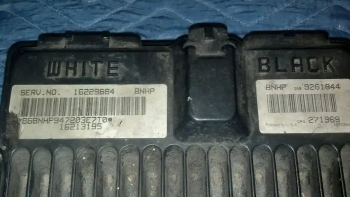
What number ECM do you have that might explain the differences in colors of the wiring.
Here's a pic

What do these numbers mean?
 

Attachments

  • uploadfromtaptalk1360652599067.jpg
    uploadfromtaptalk1360652599067.jpg
    85 KB · Views: 1,878
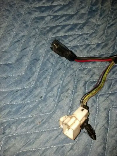
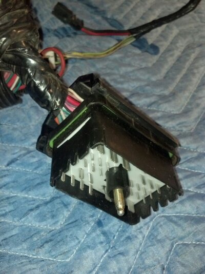
Also, I had the understanding, because of where I disconnected this connector from on the firewall, that it would contain the wires I need to tie into the cars bulkhead/firewall.


From the link above, it appears to be C100.
My "Connector Part" number is 12146324-D.

It's not listed at that link.
 

Attachments

  • uploadfromtaptalk1360654177223.jpg
    uploadfromtaptalk1360654177223.jpg
    168.5 KB · Views: 2,686
ATL Regal,

The numbers on the PCM posted tell you what year (configuration) you are dealing with. From a google search this appears to be a 1997 PCM. My PCM is a 1998 version and the wiring is slightly different, so keep in mind when I say a connector location or wire color you need to check the wiring diagrams to make sure it is the same for your vehicle.

The connector C200 is the connector which feeds back some signals back into the passenger compartment mostly indications such as oil pressure, tach, engine check light, etc. You will want to keep some of these but you have to get the diagram for your connector and figure out which ones you need. You will delete the others. Using the 1998-1999 connector and a one wire example, this is how you decide. Look at this drawing: http://lt1swap.com/1999_vortec_5.7/inli ... d_view.htm
Pin N goes to the Check engine light. It is a brown wire with white stripe, circuit number 419. Now go to this drawing:
http://lt1swap.com/1999_vortec_5.7/Powe ... %20DLC.gif
and find the Malfunction Indicator Lamp.
You can see this wire originates at the PCM Connector 4, pin 5. I know I want to keep this wire, so I will cut it at the C200 connector and label it. It is generally easier to start at the PCM and identify the wires you want.

Now for connector C100. As I said before, you generally want to work from the PCM and look at each pin/wire and decide if you need that function. So you are looking at the PCM connector C4 (black) and you go through all the pins. As an example, you get to pin 13 and see it is a brown wire. From the connector drawing: http://lt1swap.com/1999_vortec_5.7/pcm_ ... d_view.htm you see it is circuit 441, ignition positive voltage. You go to the ignition schematic:
http://lt1swap.com/1999_vortec_5.7/Powe ... %20DLC.gif and you can see the wire is routed to the IP Fuse Block (connector 100). You will trace the wire in the harness and you should find it physically goes to connector 100 position D8 as shown on this drawing: http://lt1swap.com/1999_vortec_5.7/inli ... d_view.htm
I will cut the wire at C100 and label it. I know from the schematic: http://lt1swap.com/1999_vortec_5.7/Powe ... %20DLC.gif that when I hook this up it will need to be hot in run and protected by a 10A fuse.

Now lt1swap.com has been kind enough to do all this for us. If you go here:
http://lt1swap.com/1999_vortec_5.7/index.htm
You can see he says you need 4 wires connected to C100, 2 wires connected to C200, and 4 wires connected to the underhood fuse box (UHFB). He tells you what power they need and what fuse size is need to protect the circuit.


Hope this helps,

Mike
 
nova_rookie said:
ATL Regal,

The numbers on the PCM posted tell you what year (configuration) you are dealing with. From a google search this appears to be a 1997 PCM. My PCM is a 1998 version and the wiring is slightly different, so keep in mind when I say a connector location or wire color you need to check the wiring diagrams to make sure it is the same for your vehicle.

The connector C200 is the connector which feeds back some signals back into the passenger compartment mostly indications such as oil pressure, tach, engine check light, etc. You will want to keep some of these but you have to get the diagram for your connector and figure out which ones you need. You will delete the others. Using the 1998-1999 connector and a one wire example, this is how you decide. Look at this drawing: http://lt1swap.com/1999_vortec_5.7/inli ... d_view.htm
Pin N goes to the Check engine light. It is a brown wire with white stripe, circuit number 419. Now go to this drawing:
http://lt1swap.com/1999_vortec_5.7/Powe ... %20DLC.gif
and find the Malfunction Indicator Lamp.
You can see this wire originates at the PCM Connector 4, pin 5. I know I want to keep this wire, so I will cut it at the C200 connector and label it. It is generally easier to start at the PCM and identify the wires you want.

Now for connector C100. As I said before, you generally want to work from the PCM and look at each pin/wire and decide if you need that function. So you are looking at the PCM connector C4 (black) and you go through all the pins. As an example, you get to pin 13 and see it is a brown wire. From the connector drawing: http://lt1swap.com/1999_vortec_5.7/pcm_ ... d_view.htm you see it is circuit 441, ignition positive voltage. You go to the ignition schematic:
http://lt1swap.com/1999_vortec_5.7/Powe ... %20DLC.gif and you can see the wire is routed to the IP Fuse Block (connector 100). You will trace the wire in the harness and you should find it physically goes to connector 100 position D8 as shown on this drawing: http://lt1swap.com/1999_vortec_5.7/inli ... d_view.htm
I will cut the wire at C100 and label it. I know from the schematic: http://lt1swap.com/1999_vortec_5.7/Powe ... %20DLC.gif that when I hook this up it will need to be hot in run and protected by a 10A fuse.

Now lt1swap.com has been kind enough to do all this for us. If you go here:
http://lt1swap.com/1999_vortec_5.7/index.htm
You can see he says you need 4 wires connected to C100, 2 wires connected to C200, and 4 wires connected to the underhood fuse box (UHFB). He tells you what power they need and what fuse size is need to protect the circuit.


Hope this helps,

Mike


Ok, this helps a lot! Thanks!

Now I need to find the connector diagrams for C100 & C200 for a 97 harness.. like these:
http://lt1swap.com/1999_vortec_5.7/inline_harness_connector_end_view.htm

Based on the number I found on my C100 connector(12146324-D), where can I find a diagram for it?

Also, aside from the 10 wires listed @ http://lt1swap.com/1999_vortec_5.7/index.htm I won't need any of the other wires from the C200 connector??

What will I do with them? Trace them back to the PCM and pull the pins out the connectors?
And what if they don't all trace back to the PCM?
 
nova_rookie said:
Now lt1swap.com has been kind enough to do all this for us. If you go here:
http://lt1swap.com/1999_vortec_5.7/index.htm
You can see he says you need 4 wires connected to C100, 2 wires connected to C200, and 4 wires connected to the underhood fuse box (UHFB). He tells you what power they need and what fuse size is need to protect the circuit.

Ok, I understand the part about looking at all the pins/wires on the PCM connectors and tracing the ones I need/wanna keep to their corresponding connector (C100 or C200) because these would need to go through the firewall to my instrument cluster or steering column, but I don't understand how the Underhood Fuse Block comes into play.

Please correct my reasoning if I'm wrong.

I'm thinking that the battery supplies power to the UHFB, wires from the UHFB go to the PCM and all the connectors that need power, wires from the connectors supply the PCM with data that gets processed and the PCM makes adjustments as needed, some of this data is also sent to the USER/DRIVER in the form of gauge readings. Correct?

I was thinking that I would just need to find out what wires from my harness (on C100 & C200) would I need to cut off of the connector and connect to the Regal's firewall wires, example: find out which wire is hot in run and start and connect it to the corresponding wire on the Regal's firewall, where it would go inside the car to the fuse box, then to the keyed switch. Same for the Tach, Oil Pressure, Water temp, Fuel level, Neutral safety switch signal (so the dash shows which gear I'm in), then I would work on Cruise control & A/C. Correct?
 
Status
Not open for further replies.

GBodyForum is a participant in the Amazon Services LLC Associates Program, an affiliate advertising program designed to provide a means for sites to earn advertising fees by advertising and linking to amazon.com. Amazon, the Amazon logo, AmazonSupply, and the AmazonSupply logo are trademarks of Amazon.com, Inc. or its affiliates.

Please support GBodyForum Sponsors

Classic Truck Consoles Dixie Restoration Depot UMI Performance

Contact [email protected] for info on becoming a sponsor