1980 Pontiac LeMans Station Wagon - G-T-faux (stuck with it, and can't shake it... like a bad case of herpes)

Status
Not open for further replies.
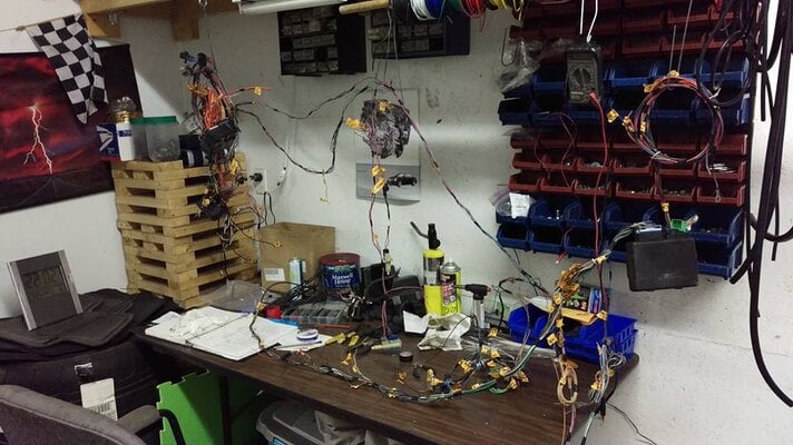
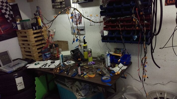
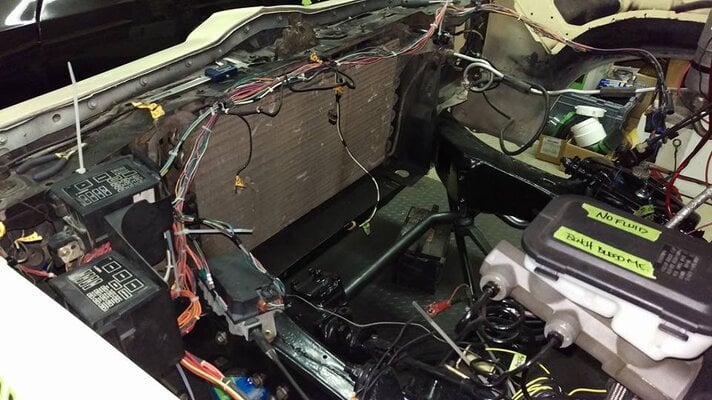
I am done tracing wires... for now. I just have to figure out how to get them into the cabin - as the fuse block is under hood and a bunch of connectors need to pass through the firewall and there isn't a spare 3"x2" pass through. Hmm... might just have to cut and splice. Again.

I am going to have to re-loom it after it is all laid out.

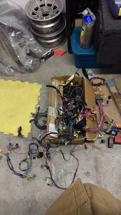
I still have to breakdown and clean up the PCM/engine/trans harness. Yippie.

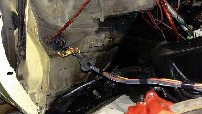
I am reusing the speedo cable pass through and grommet for wiring on that side; I've already cut the wires that I needed to go through on the driver's side. I might try and source some square Type 2 weather pack connectors. Might.

Then I drilled a 1.5" hole on the passenger floor where the radio antenna would normally pass through and reusing the grommet from a '91 Z28. Which made me wonder how the radio worked if the fender antenna was run. It isn't. Just a snipped wire dangling inside the fender. FML I thought. Then I noticed that it has a windshield antenna - go figure. But, then again I haven't touched this car for months.

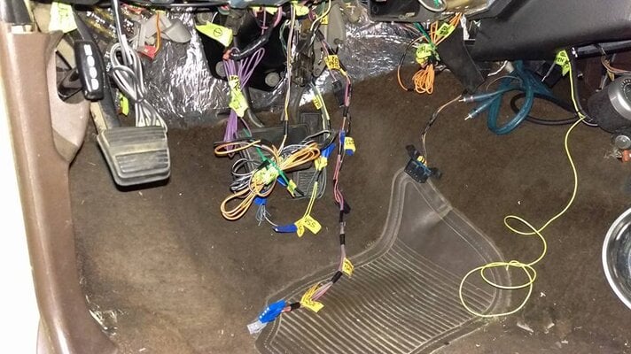
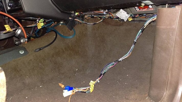
Here is where I am at. Ran the harness under the dash, the BCM is in the kick panel and all the spare "future consideration" wires are in the plastic run under the sill plate, the neutral safety switch wires are lined up with the shifter, the ALDL and brake wires are in place. I do need to remove the stock cruise control box as it won't be needed.

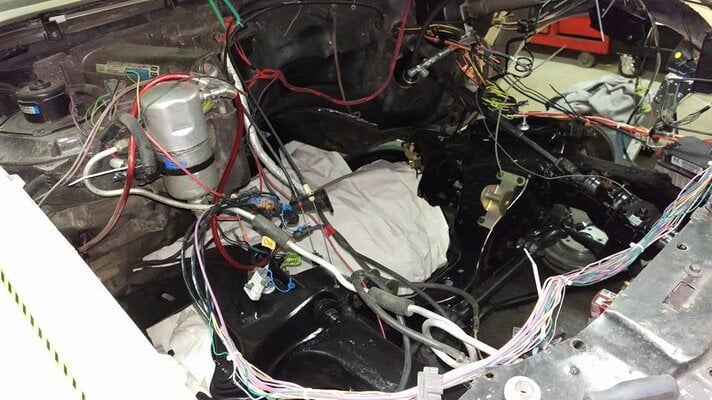
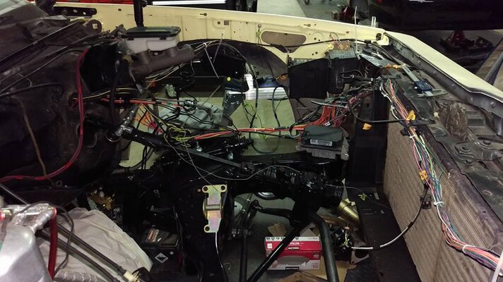
I also laid out the fuse blocks and the PCM/ECM wiring; and if you can't tell I need to extend the wires for the cruise control and friends about 30" or so. Then I grabbed the cruise control module and gave it a trial fit. And finally since I was in such a good mood I decided to treat myself to running the throttle cable - I hooked a spring to the engine side and sat in the car making vroom vroom noises and rowing through the notional gears.

And that pile of wires is the aftermath of a month's worth of evenings and weekends.
 

Attachments

  • wires.jpg
    wires.jpg
    84.9 KB · Views: 297
  • wires2.jpg
    wires2.jpg
    69.4 KB · Views: 303
  • wires3.jpg
    wires3.jpg
    80.3 KB · Views: 284
  • wires4.jpg
    wires4.jpg
    87.9 KB · Views: 293
  • wires5.jpg
    wires5.jpg
    70.3 KB · Views: 290
  • wires6.jpg
    wires6.jpg
    70.7 KB · Views: 292
  • wires7.jpg
    wires7.jpg
    91.3 KB · Views: 286
  • wires8.jpg
    wires8.jpg
    85.1 KB · Views: 275
  • wires9.jpg
    wires9.jpg
    88.7 KB · Views: 285
  • Like
Reactions: Blake442
Its alive!

Electronically at least. I got the PCM to talk to me, scanned it and wrote to it. I was making sure that VATS was turned off, had to set it to "P/N" for the neutral safety switch on the shifter, and turned off the "shifter lock" function (just in case).

I also finished extending the wires - so very un-engaging. Now I just have to finish routing the wires, wire in the Boost-A-Pump/hot wire to the fuel pump, terminate the SpeedHutgauge leads, connect the cruise control and AC wires, securely mount the underhood fuse blocks and the PCM, and finish looming it up. Ugh.
 
  • Like
Reactions: liquidh8
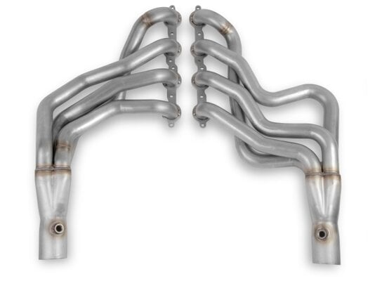
I decided to splurge on something for the wagon: Hooker 1-7/8" LS swap headers... in stainless.
 

Attachments

  • 2333-7HKR.jpg
    2333-7HKR.jpg
    67.5 KB · Views: 293
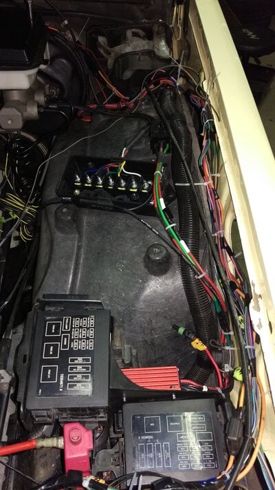
Been battling a serious cold so progress was slow this weekend. That being said I did manage to connect all of the main circuits to the spare/unused Maxi fuses at the LS1 fuse-blocks - eliminating the need for fusible links; including the BCM. I also wired up the Boost-A-Pump with a dedicated relay and 10ga wires for the power. Because sending 16 volts down a 0.5mm wire just didn't make much sense; I am still undecided if it will be a 10ga or 8ga wire going back to the tank. Either way it sure beats using just a hotwire. The BAP will be triggered by the nitrous kit when activated - I just have to decide if it is going to be on the hit or when the system is armed.
 
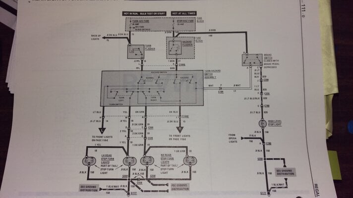
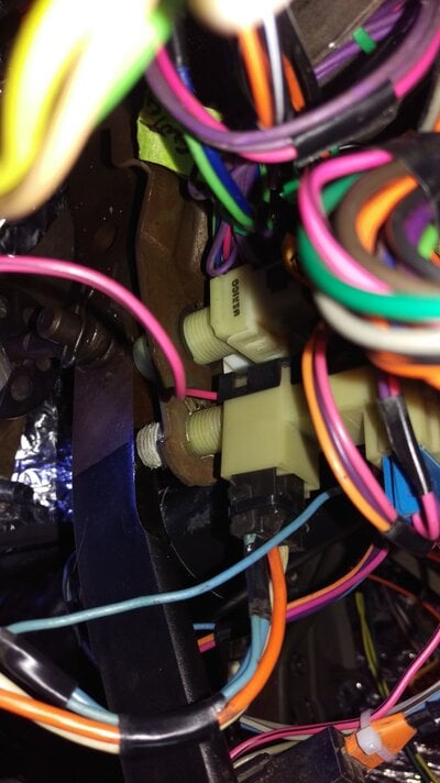
Does anyone know if it is normal to have about 10 volts at the Lt Blue wire (next to Org, and Wht) coming off the brake switch harness with the Key On? My diagrams show that this is for the 3rd/High Level Brake light. I get the full 12 volts across the switch when the pedal is pressed. This 10 volt thing is driving me crazy!

Okay so here is the deal with the Lt Blu wire:

Key Off = 0V
Key Off & Brake pedal depressed = 12V
Key On = 10.5V (settles in at around 9.5V)
Key On & Brake pedal depressed = 12V

The diagram attached (straight out of the 1986 Buick service manual) does not indicate a constant voltage of any kind on that Lt Blu wire. So either I have a short, a crossed circuit getting fed from a Key On source, or maybe a bad or disconnected ground? All wild *ss guesses here. The funny thing is that I have no real need for that circuit as the main harness is from my Monte Carlo - as wagons do not require/have provisions for the third brake light (aka High Level Stop Light) normally - and could just clip the wire and call it a day. Because what I do need is to be putting 12V to the piggybacked Lt Blu wire when the brake pedal is depressed for the Camaro's cruise control module.

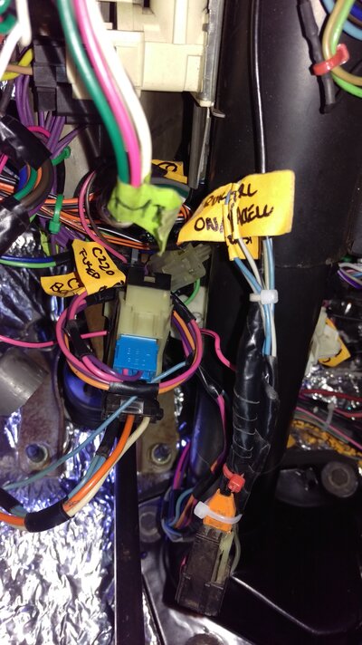
I've attached photos of the brake switches I am using for reference. The top one is OEM to a '02 Camaro and the bottom one is OEM to an '87 MCSS; the wires in the rear portion of the bottom switch are from the '02 Camaro cruise control.

So if anyone can take a moment and check the following voltages for the Lt Blu wire I would really appreciate it.

Key Off =
Key Off & Brake pedal depressed =
Key On =
Key On & Brake pedal depressed =

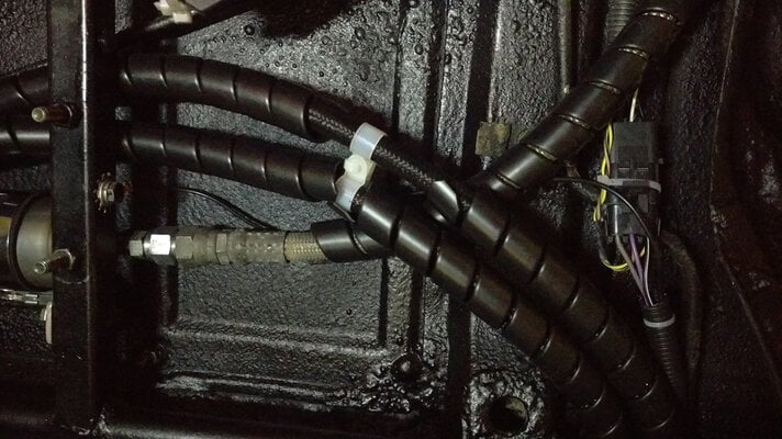
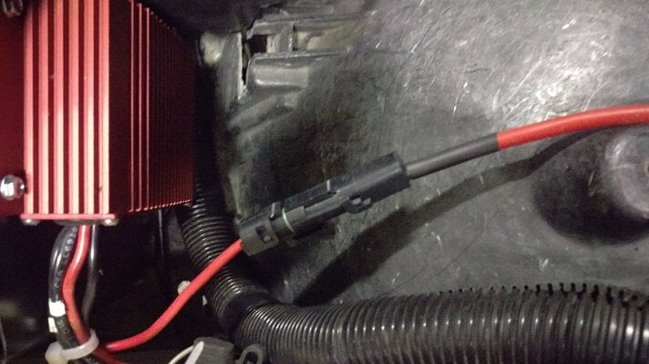
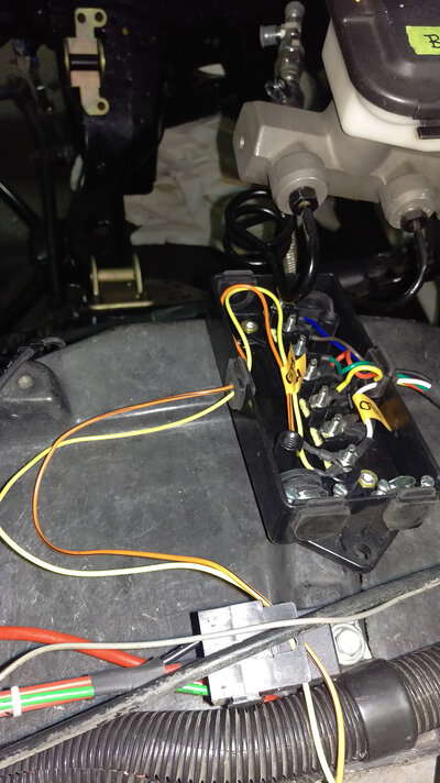
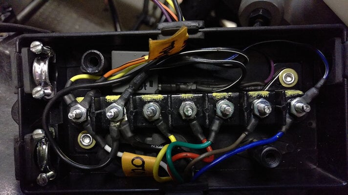
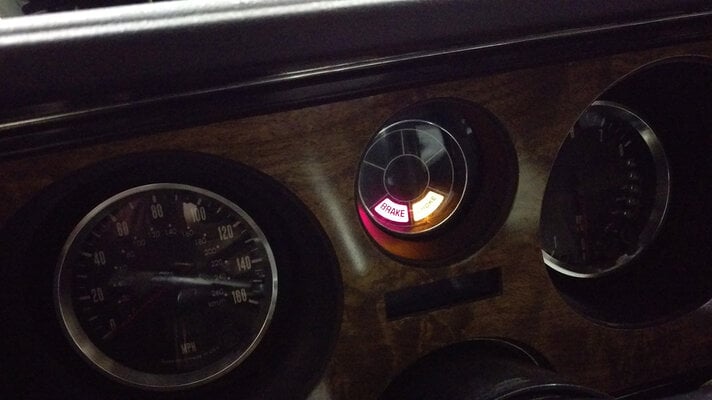
Oh and here is how the wiring is laying down from the Camaro fuse blocks back - getting there slowly; cruise control is wired up. Even hooked up the SES light feed from the BCM to the dash too.
 

Attachments

  • IMAG1618.jpg
    IMAG1618.jpg
    2.7 MB · Views: 275
  • IMAG1620.jpg
    IMAG1620.jpg
    3 MB · Views: 264
  • IMAG1622.jpg
    IMAG1622.jpg
    2.7 MB · Views: 276
  • IMAG1619.jpg
    IMAG1619.jpg
    3.8 MB · Views: 269
Completely forgot to update this here since there was zero feedback. Done knocking the sand out of my vag...

So on Dave's advice I tried to light a light with the ~10V present in the circuit. And...

Using a 194 bulb-sized socket, and a 194-sized LED and a standard 194 incandescent bulb I get the following results:

1. Key On & Using the LED = the faintest of illumination;
2. Key On & Using the standard bulb = no illumination;
3. Brake pedal pressed & Using the LED = blinded Mike; and
4. Brake pedal pressed & Using the standard bulb = the sweet warm glow of a generation lost.

Looks like it is a possible ground issue. I am going to try a jumper from the frame to the body to see if that aids the situation.

In other news I can now run a lead for a third brake light - wagons need all the help they can get.

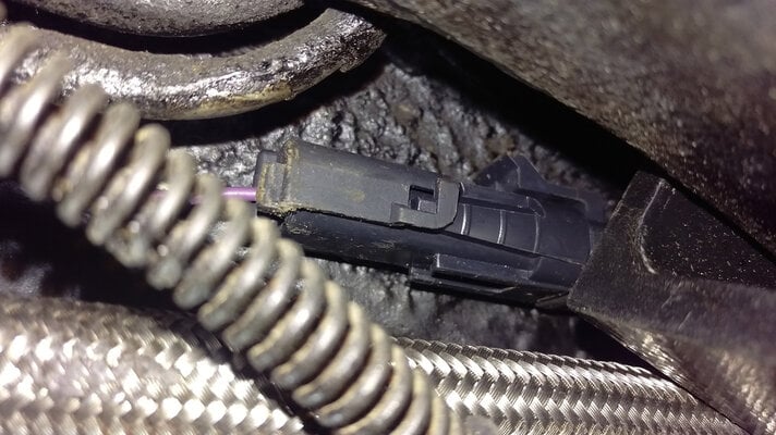
Finally got the fuel pump hooked up. I had to create a breakout harness for the fuel level sender signal and low reference wires which go back to C230 for the ECM (which runs back to the sending unit). Totally unnecessary for a swap, but I do want to ensure total functionality wherever possible. I also elected to run an 8 gauge wire from the BAP to the pump to carry the 16+ volts and whatever amperage is drawn. To the credit of Spectra they used some pretty hefty wiring in the harness on the sending unit.

I also had to create a tach lead off of C105 (pin G) so that I could feed my tach, N20 window switch, and the remote starter. This wire does not exist when using a non-traction control harness.

2995297-stewie+more+you+know+meme.png
 

Attachments

  • 115.jpg
    115.jpg
    419.6 KB · Views: 273
  • 116.jpg
    116.jpg
    358.8 KB · Views: 267
  • 117.jpg
    117.jpg
    371 KB · Views: 259
  • 118.jpg
    118.jpg
    404.6 KB · Views: 275
I don't know how you do it ( sandy vag and all ) LOL as its leaps and bounds more then I would ever attempt.
**** ! It took me a year to get the body mounts swapped on my car and even then I have only done 6 of 14 so far.
 
Ha! That makes two of us. Especially when I take a 3 week break in the midst of some complex work. I do miss carbs and distributors.
 
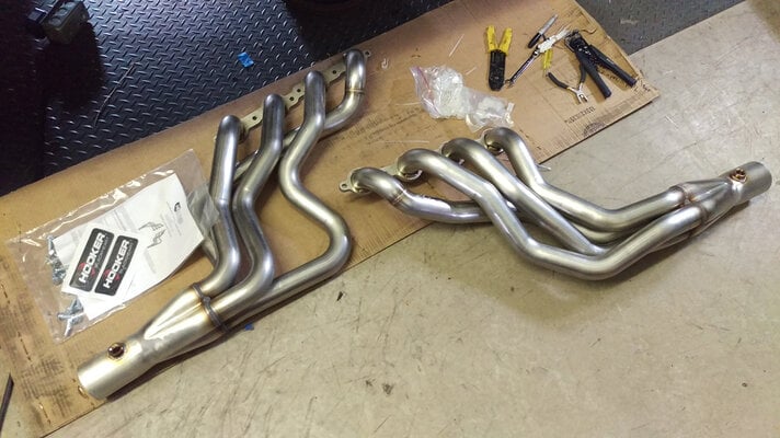
So the Hookers showed up; and who doesn't love Hookers?

I wired in a micro-relay to ground the "CHOKE" light when the cruise control is activated. There is a diode on the signal wire to the relay to ensure that it is only listening and cannot back feed any interference into the ECM (you know, just in case).
 

Attachments

  • headers.jpg
    headers.jpg
    389.6 KB · Views: 269
  • cc1.jpg
    cc1.jpg
    363.3 KB · Views: 270
  • cc2.jpg
    cc2.jpg
    260.3 KB · Views: 277
Status
Not open for further replies.

GBodyForum is a participant in the Amazon Services LLC Associates Program, an affiliate advertising program designed to provide a means for sites to earn advertising fees by advertising and linking to amazon.com. Amazon, the Amazon logo, AmazonSupply, and the AmazonSupply logo are trademarks of Amazon.com, Inc. or its affiliates.

Please support GBodyForum Sponsors

Classic Truck Consoles Dixie Restoration Depot UMI Performance

Contact [email protected] for info on becoming a sponsor