Re: 500 Caddy into El Camino
It’s finally time to actually get the 500 in the engine bay. The way I’m doing it is not the only way to get it stuffed in there, there may be easier ways or shortcuts that will work better for someone else, but this is the way I did mine. I hope this is not overly detailed, but I wanted to cover as much as I could for those who have never done an engine swap before.
In my case I wanted to do it with the front clip and inner fenders on the car to make sure that there would be no surprise interference problems. Now that I have seen that there won’t be I know that I could have left the front clip off and it would be a bit easier to do the swap.
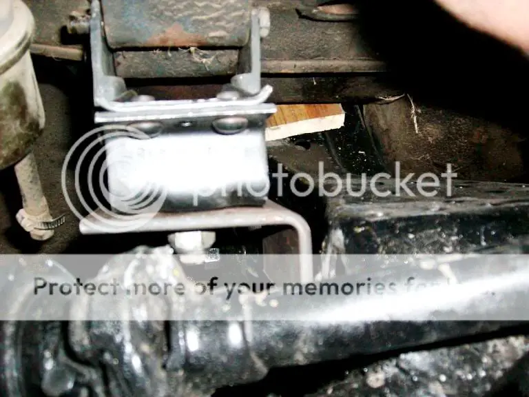
I’m using the basic engine swap kit from MTS as the basis for my motor mounts. While it may seem a bit expensive for a few pieces of metal and a couple of motor mounts when you figure the time involved in finding the bits and pieces, cutting bending and drilling them it really is worth the money to me to have it as a starting point. While I will be welding mine in, from the looks of it you could also make them a bolt on affair with some extra work (in the event you don’t have access to a welder. (Picture shows brackets for 1 side).

I did notice a couple of things about the kit that I felt I did need to modify. The first is the size of the hole for the motor mount stud. The stud is swedged into the mount and the raised portion does not allow the plate to sit flush on the mount. I cured this by relieving the hole a bit with a die grinder. The other thing I noted while installing the engine is that the motor mounts are splayed. In the event that the engine ever has to be removed/reinstalled from the car it would be physically impossible to do by just removing the motor mounts stud nut. You would actually need to unbolt at least one if not both of the motor mounts from the engine in order to get it out. Although I haven’t done it at this point I will be turning the holes into slots to allow the engine to be removed and re-installed with the mounts attached.

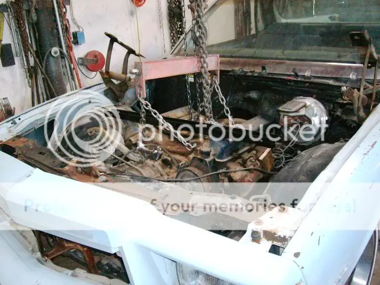
I’m doing this swap with a chain hoist and engine leveler because I have them and it does make it a lot easier. While it most assuredly can be done with an engine hoist, I just feel a lot more comfortable doing it this way and I don’t have to worry about the engine hoist leaking down over time while I make adjustments. As I put the engine and trans in as a unit the engine leveler makes the job a lot easier as the unit has to go in at a pretty steep angle (especially if you’re using a long tail shaft version like I am).
If you are using the leveler, make sure you attach it to the next to the last intake manifold bolts instead of the most rear bolts, otherwise the rear chains hit the firewall before you can get the engine back far enough.
Prior to actually setting the engine in there are probably a few things you will want to do in the engine compartment besides just removing the old engine mounts. One is remove the transmission linkage from the steering column. It interferes with the head on the driver’s side and won’t allow the engine to go back as far as it could.
You may also want to either remove or at least wire out of the way the original fuel line that comes thru the frame (and is on the passenger (wrong) side anyway). It makes it difficult to get the new motor mounts brackets slid into place while setting things up.
When I go this El Camino the AC has already been removed and a delete plate installed. Personally I like the way it cleans up the engine compartment so I’m going to be installing an aftermarket behind the dash AC/Heat unit. If you are retaining the original AC unit I understand that there will be an interference problem with the AC box and pass side valve cover. This probably leaves you with a couple of options when setting in the engine.
One way would be to completely remove the box and accumulator from the fire wall while your setting the engine in (which would give you a better view of your clearances in the right rear corner of the engine compartment).
It MIGHT also be possible just to remove the passenger side valve cover and gain enough clearance that way to get the engine in and mounts built and then trim the box as needed on the final install.
Finally you could trim a little bit off the box as you go until the engine sits where you want and the go back later and fiberglass in the hole.
As far as getting the engine ready to install, about the only thing I did was to remove the water outlet nipple in the back of the driver’s side head and pull the AC compressor, carburetor and distributor to make room for the engine leveler chains. I also pulled the oil filter so it wouldn’t interfere with the sway bar during the install. I left the exhaust manifolds, fuel pump attached.
As I did not know how the motor mounts would fit best (with the stud up or down) I left these off until the engine was close to the final position and found they fit best with the stud up high, and then bolted the plate that came with the MTS to the motor mounts. Knowing that now if I were to do one in the future I would bolt the mounts and plates to the engine prior to setting it in the engine compartment.
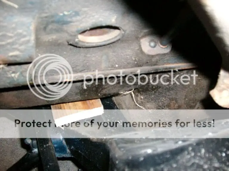
There were a couple of things I did to help make positioning the engine a bit easier. One was to set a short section of 1” (actual dimension was 3/4 “ thick) board on the crossmember. This gave me the height I wanted the engine to sit at and helped stabilize the engine while I was locating it. Once it is removed after the mounts are built there is good clearance between the pan and crossmember. While I would prefer the oil pan to sit up at least level or a little above the crossmember, the El Camino will sit at a little higher tan stock ride height so this should be OK.
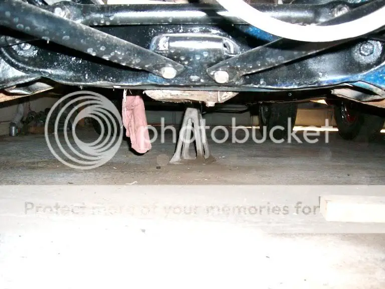
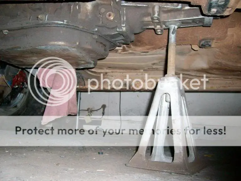
I also positioned a small screw type jack stand (normally used for leveling mobile homes) under the rear of the transmission. This allowed raising and lowering the rear of the transmission and is a bit more precise and less in the way than a floor jack.
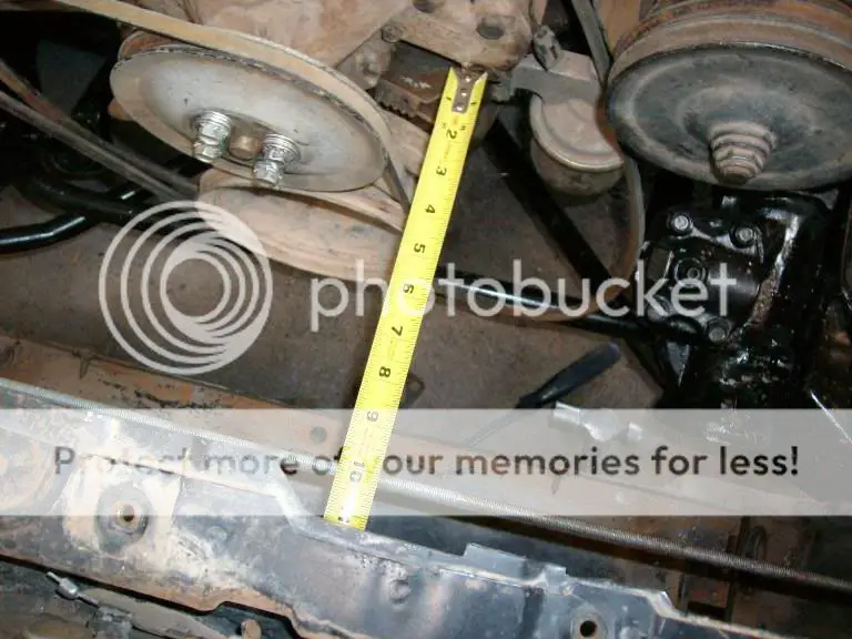
With the engine set at the height I wanted it the next step was to move it back as far in the engine bay as possible. The distance you can move it back is determined by how much room you have between the back of the drivers side head and the fire wall. You want to remember that with the stock rubber motor mounts the engine is going to rock somewhat so you need to make sure the there is sufficient room not to rub on anything. This picture shows the amount of clearance I left for myself.
The Cadillac engine is pretty wide especially at the exhaust manifolds and in order to get sufficient clearance on the steering column I offset it to the right about an 1 1/2” .
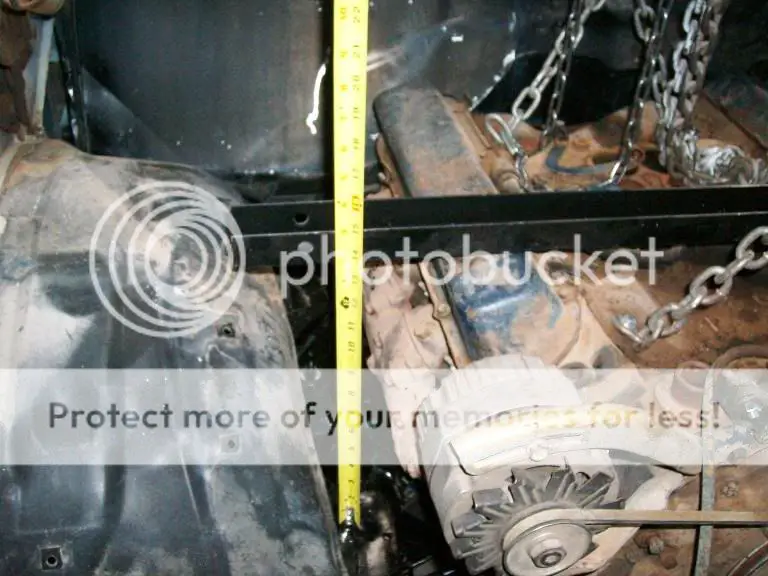
With the clearances set the next thing was doing the final tweaking and leveling to make sure the engine sits square in the engine compartment. For leveling the engine a lot of guys use a bubble level, which works well as long as the car is sitting on a level floor, has the same size front tires and the springs don’t sag more on one side than the other. As my garage floor is slightly slanted I prefer to lay a straight piece of metal across the engine and make measurements from the top of the frame rail to make sure the engine sits level from side to side.
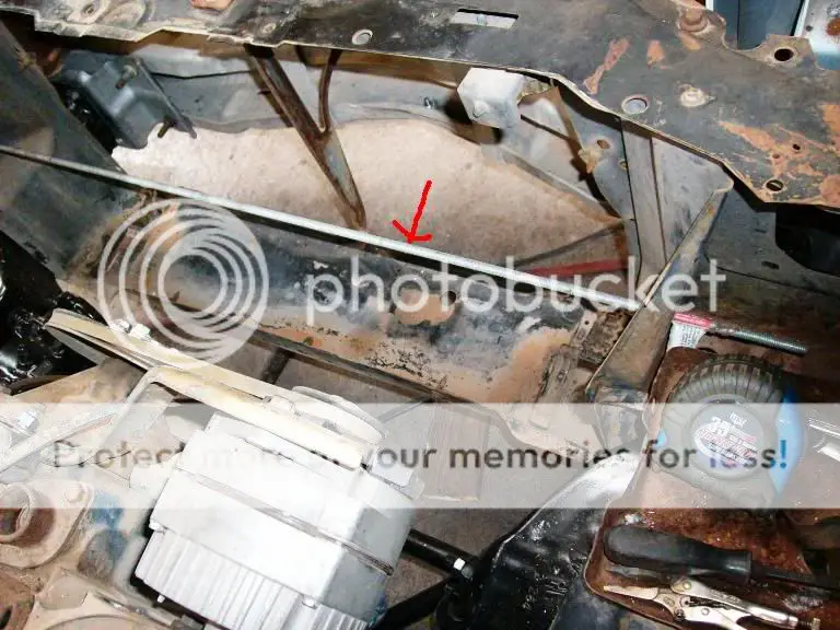
To make sure the crankshaft centerline sits straight I also measure from a fixed point on the frame to points on the left and right side of the engine, in this case I ran a piece of straight threaded stock thru 2 existing holes in the core support (I had already measured the core support to ensure it sat square in the frame).
I then took measurements from the 2 lower water pump bolt bosses which should be square to the block.
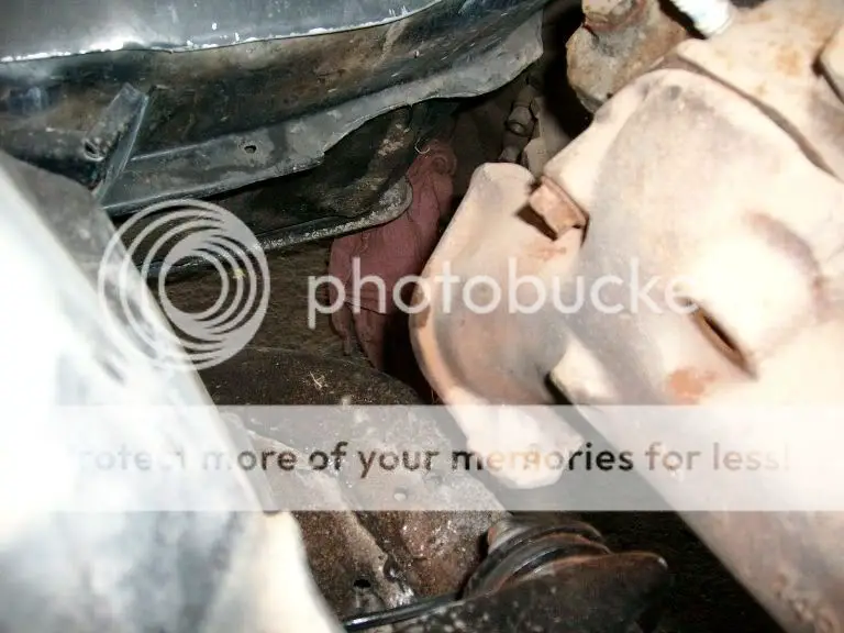
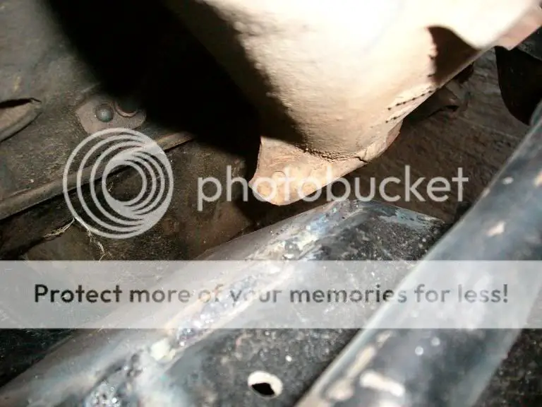
Clearances were close on both exhaust manifold outlets and I’ll probably have to relieve the frame slightly for clearance, which was not unexpected after seeing some other peoples builds.
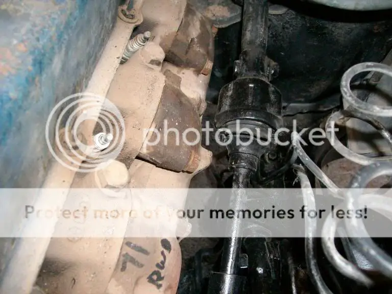
Clearance on the steering shaft is close but adequate.
After I was satisfied that everything was square and had the best clearances I could get, I vicegripped the 2 bracket halves together.
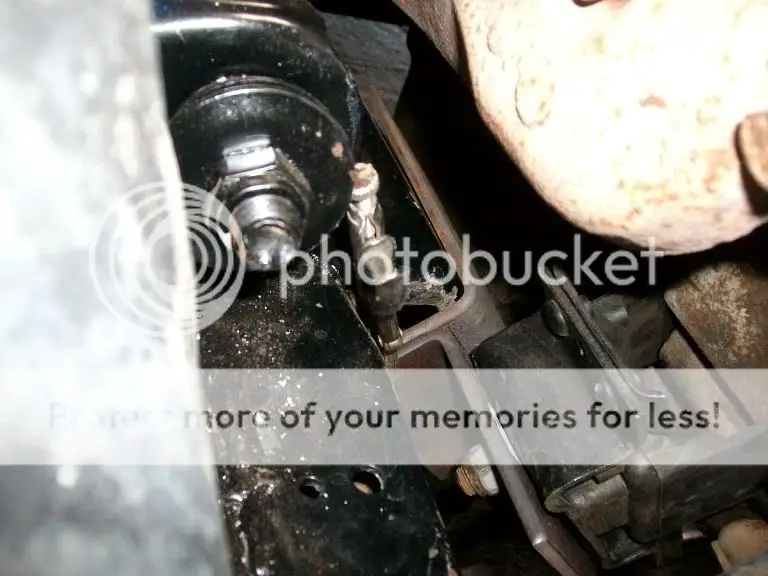
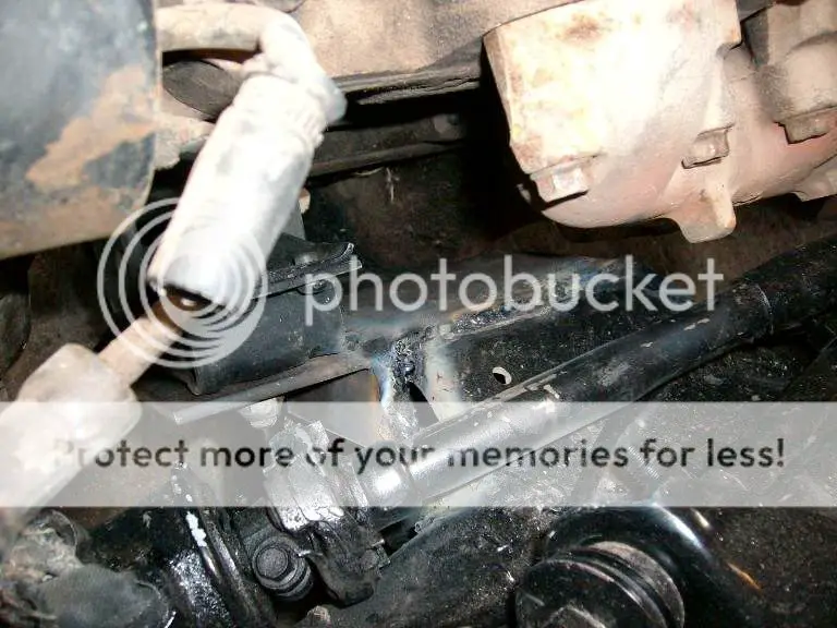
And the tacked the brackets together and to the frame. The welds are a little ugly right now as I used my stick welder as I’m more comfortable that I’ll get good penetration. Once the engine is back out I’ll final weld the brackets, add gussets, grind welds etc. for now it good enough to hold the engine in position.
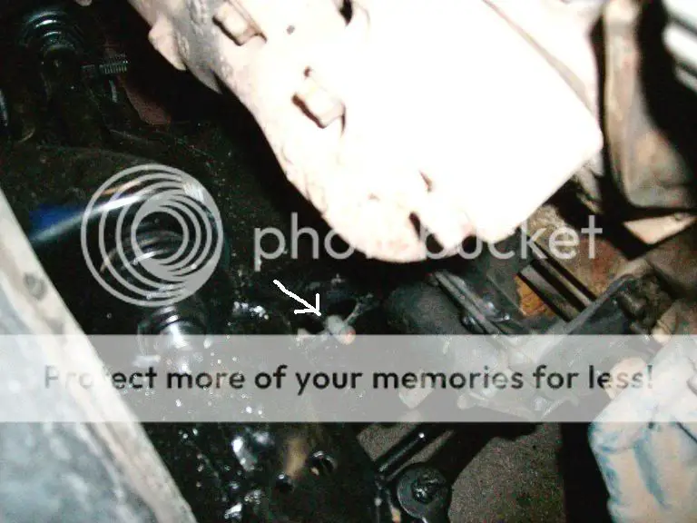
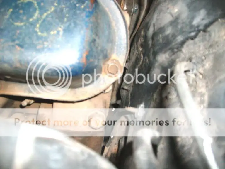
The last interference problem I ran into was the oil filter, as with other people who have done this swap, I found I cannot get a filter on the oil pump due to sway bar interference. Some of the swaps I’ve seen space the sway bar down to cure this. As I will need a new oil pump for this build anyway, I’m going to order one from a later 425/368 that is supposed to tuck the filter closer to the block and see if that will work. I’ll keep you posted on that one.
And here it sits for now, I want to run a 1” spacer under the carb and a dropped base air cleaner on the stock manifold. With the Monte Carlo hood having some extra clearance I just might make it. I don’t think if I was running stock front sheetmetal it would work without a hood scoop or loosing the spacer though.
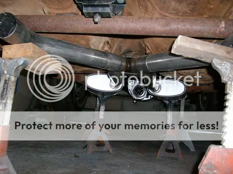
The next major project is going to be the crossmember and exhaust, but that’s for another weekend.
