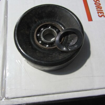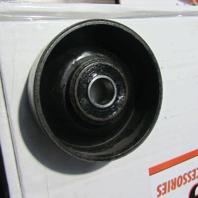


So a page or two back I believe that I mentioned the ongoing search for a bearing end-play/preload setting fixture that I had fabricated as much as 20-25 years ago and now could not find. While I am still keeping my eyes open for it, I also decided not to wait for good fortune and serendipidity to kick in and that it wouid likely be easier to manufacture a new one.
For the deck material, I chose, like I did with its predecessor, to use 1/4 inch flat plate. I was able to source a section that was, 4 inches wide and 17 inches long. Clipping a 3 inch long piece from that will give me a final length of 14 inches for the base and 3 inches for the tab/ear that will be attached to the base to allow me to mount it in a vise.
What you see in the pictures above is the base, sitting in the drilling clamps on my press. At this point all the mill scale and foundry debris has been ground away from both sided of the plate and this, the side or surface that will be visible, has been treated to a cross-hatched finish that removed most of the grinding marks left from the descaling process.
At present, the bore for the bearing spindle to be fitted sits at 5/8ths inch. The final bore for the spindle will be 47/64ths, which is a very close match in diameter to that of the spindle itself. Technically, the hole being cut ought to measure .7500 as the spindle will be made from 3/4 all thread. However, a quick diameter check of the all-thread showed that, while it accepted a 3/4 hex nut, and was rated as being 3/4 in diameter, it was physically produced a few thousandths under size; most likely for ease of insertion into a hole, or for threading. Since a 47/64 HSS, 1/2 inch shank drill bit is, as of right now, not an item in my tool inventory, I have to wait until my supplier brings one in for me. So the whole thing can just sit in the clamps for now.
When done, this device will be my Mark One, Mod One version, as opposed to its Mod Zero predecessor, simply because with the first one the foundry scale finish was left untouched and the mounting ear was mechanically attached by drilling it for tapped holes and using socket cap screws to create a mechanical connection. This one will display a nicer, cleaner, more professional finish and have the ear welded in place; a faster simpler process that takes less time and offers a more permanent connection.


So this nasty looking lump is actually my solution to how to properly mount the evaporative charcoal canister in my G-10. The back story on this is that I had had to remove the can due to needing to use its hardline for the return line to the tank for my FI TEch TBI system. That work around, suggested by FI Tech as part of their installation instructions, was never a good idea and led to all kinds of venting issues for the tank itself. Just another nail in the coffin of why I am not a fan of the FI TEch TBI injection units.
Since the TBI system is now an ex-system, that is it has ceased to be, and an AVS carb now rules in its place, I can once more re-plumb the evap tank so it can do its job again. Problem for me was that 40+ years of time and age have rendered mounting brackets for 1980 GM vehicles, apart from C-series trucks, pretty thin on the ground. I was able to scare up some newer versions but none of them really would fit or could be mounted in the existing location easily, so a Plan B had to be made.
Plan B, as you see above, was to take the bracket that most closely matched what I needed and modify its mounting channel to fit the pocket in the fire wall. In one of the pictures you can see the original mounting channel that I cut away using a hack saw. The issue with it was that it tapered from end to end and that would put the bracket on an angle once bolted to the radiator cradle. The mounting pocket on the cradle was equally deep from top to bottom so the height of matching channel had to be equal from end to end as well.
]
For the new channel, i was able to harvest a section of channel shaped sheet metal from a brace that used to be part of a sliding van door. Hey!, waste not want not, and the general shape matched what I needed. I did have to trim and spread the ears out a little but that is what fabrication for old stuff is mostly all about.
I make no apologies for the welding. Both pieces did get ground free of paint and rust as much as possible, but the basic material wasn't much thicker than 19 gauge and has gotten thinner over its life and wear. The first tacks were run at a 22 gauge settiong on the MIg but that proved too cold and I ended up using the 20 gauge setting instead. They still look ugly and bubbly; way too much contaminated metal even after using a grrinder on it but about par for the course. This is not a structural component and it will be mostly invisible once set in place and bolted down.
The plan B, part two, is to now dress all the tacks down to make them and the seam they will become, as smooth as possible on both sides and then figure out where the holes for the bolts should go. I may have to tack in a couple of nuts on the bottom of the channel or go the other way and mount them on the cradle pocket and run the bolts in from the engine side. The second way would make removal in the future a whole lot simpler as it would avoid having to remove the grille and associated bits to gain access.
Today is something of an R&R day as most of all this was done yesterday and outside the garage for the sake of space to maneuver. You don't notice the cold when you are active but your body sets a price to pay when you get back inside and warm.
Nick
Last edited:


