What did you do to your non-G body project today? [2022]

Status
Not open for further replies.

g0thiac

G-Body Guru
Sep 6, 2020
939
582
93
Did probably the most sketchy electrical work, not too proud of that lmao.

As the week before like I said, I didn't disconnect my battery, and the bolt on my alternator touched the block and started a small fire there.

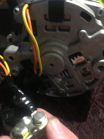
Well, after trying to remove the old alternator cable a few days ago it pulled out the damn positive terminal too. It had welded itself so bad that the threads were destroyed. I am glad I discovered this, because had that terminal got pushed out while driving there could have been another huge fire.


That said, I was able to put in a bigger bolt, and solder wires to it, also because I was nervous about if it would ground to the case or not, I used a LOT of electrical tape.

Also did a voltage test while spinning it up, to make sure it worked. Completed a continuity test too to confirm no short circuit.

I only plan to use this alternator to get me home which is not even a 2 minute drive, and swap it out also.
 

Attachments

  • 8458BC08-833B-4245-ABCC-924ED09236C1.jpeg
    8458BC08-833B-4245-ABCC-924ED09236C1.jpeg
    1,011.2 KB · Views: 74
Last edited:

Ribbedroof

Comic Book Super Hero
Supporting Member
Jan 4, 2009
4,904
7,013
113
Wellston, OK
Assembled these bad boys and drank a brew. Much easier to shuffle 1 of the projects around the garage without having to start it up. Also got all the ice fishing gear ready for tomorrow.
Iron casters?
 

Ribbedroof

Comic Book Super Hero
Supporting Member
Jan 4, 2009
4,904
7,013
113
Wellston, OK
Nice. The ones locally have plastic casters and don't roll worth a damn
 

CopperNick

Comic Book Super Hero
Supporting Member
Feb 20, 2018
3,357
3,018
113
Canada
Omron and Universal Relay terminal comparison picture.jpg


So, Draftsman I am not. What you see here is a rough drawn comparison between the terminals listed on an Omron version relay and the ones I normally work with and use in my older vehicles. (Bosch or similar) I've already tagged the Bosch terminals for what they do BUT....

BEing able to do this for the Omron is just a double trifle more difficult. This is what shows up in my S-10 and most similar newer GM vehicles of that vintage. For the manually inclined, Yes i do have the electrical service manual but interpreting it can be complicated because it does not show full wiring diagrams, it is more a case of wiring references sending you to other wiring references, most of which include a a side trip to a picture of the harness plug.

So, can anyone tell me, or has anyone ever taken the time to identify what Omron terminals 1-5 do for a living; and yes there is a cute picto-gram on the case side that might make Og the caveman happy but does little for me in a positive manner. For the inevitble visitor who wonders why not just go with the Bosch, I am trying to make this upgrade to my S-10 door windows and locks as factory as possible and the Omrons come already plugged into their own chassis with wiring already there so that portion of the install is sort of plug in by way of attaching it to the main fuse/block-relay centre located under the hood.

References?
 

CopperNick

Comic Book Super Hero
Supporting Member
Feb 20, 2018
3,357
3,018
113
Canada
Amp: What is going on is an upgrade to an existing harness to introduce electric power windows into my S-10. The biggest hassle isn't the doors, it is lacing the new wiring into existing harnesses and getting it to come and go like the factory did. Accessing the wiring chases in the A pillars is not easy at all; it may take removing the front fender!! to gain sufficient and open enough access to deal with the fire wall. The only reason I am back at this project is to kill time while my body heals from pre Christmas surgery; this is a mind exercise not a hammer and welder day at the races here.


Nick
 
  • Like
Reactions: 1 user

Built6spdMCSS

Geezer
Jun 15, 2012
5,804
9,715
113
Florida Beach
So, can anyone tell me, or has anyone ever taken the time to identify what Omron terminals 1-5 do for a living; and yes there is a cute picto-gram on the case side that might make Og the caveman happy..
Since you know what 30, 85, 86, 87, 87A do..

20220102_170833.jpg


I might have a couple..🤣

20220102_170943.jpg
 
  • Haha
  • Like
Reactions: 1 users

Built6spdMCSS

Geezer
Jun 15, 2012
5,804
9,715
113
Florida Beach
So with these here, something that I've always done from my research and what I was taught..

85- Switched Ground, always try to switch the ground side. Yea it's not barely any Amps coming through the 12 side, just habit.
86- Fused ignition 12V.

That is how I've always done my relays unless it was something that needs constant power on 86 to work, which there aren't many circuits needed for that.

RELAY.jpg
 

CopperNick

Comic Book Super Hero
Supporting Member
Feb 20, 2018
3,357
3,018
113
Canada
For #85 and # 86, I elected to revisit one of the wiring reference sites on the interwebs and those numbers were listed as being associated with those functions. I haven't been able to reference my wiring bible for how I actually did them so many years ago as yet.

Thanks for the picture and the 1=, 2=, etc. Things got more complicated just after I posted this request. I did elect to go back to the service manual electrical volume and lo, and behold, I had managed at some time a few or more years ago to equate the aftermarket terminal numbers with the system GM employed. What I also relearned was that, although GM had used a 5 pin socket for its relays, the function of the relay changed the numbering on the pins according to what circuit they were part of. I also learned that identical relays could be wired for two grounds or two power+ leads, each of which fed the same terminal number; i.e. two orange or + power wires, each one of which fed a 1850 terminal id, in the real world, term 1850 is term 87 and 87A. It would seem that the relays can be wired to handle multiple power out situations where one relay is expected to actuate two devices at the same time.

All this tells me that I only have enough relays for one side of the vehicle because, apparently, there is one relay for "Lock", and another for "Unlock". The only way I can see to running the two is if they both are set up for double actuation using the 1850, or 87/87A convention. This mind twister may be why I elected to shelve this at the time. I am also still no further along in identifying the structural chase in the A pillar that will take my wires through the firewall and into the engine bay where the relay chassis is to be found. As this truck was never fitted with e-windows and locks, I may have to power the sub relays by using a fused jumper off one of the accessory terminals.

Oh, yeah, none of this solves how the power gets to the window regulators. I have them, their rocker switch assemblies in their door plates and all the associated harness but none of that show any architecture for a relay. Wonder if they are direct power somehow? Even the ones that I retrofitted to my Van got a breaker added to the circuit and I may go back and adapt them to a relay as well; less draw when the van is not running.


Nick
 
Status
Not open for further replies.

GBodyForum is a participant in the Amazon Services LLC Associates Program, an affiliate advertising program designed to provide a means for sites to earn advertising fees by advertising and linking to amazon.com. Amazon, the Amazon logo, AmazonSupply, and the AmazonSupply logo are trademarks of Amazon.com, Inc. or its affiliates.

Please support GBodyForum Sponsors

Classic Truck Consoles Dixie Restoration Depot UMI Performance

Contact [email protected] for info on becoming a sponsor