What did you do to your non g-body project today [2025 edition]

Took it to the gym again and then dinner, had been hoping to get her on the highway to stretch the legs a little but dinner took so long decided to just go home afterwords
1741782560369.jpeg
 
put a new rain cap on my shop chimney.

1741784684742.png


And i tried to sweep out the shop, but the wind was fighting me the whole way.

1741784763214.png
 
Last edited:
Why not pull your current directly from the battery and use that coil wire for actuation only? Or am I not quite picking up what you're putting down?
Fair question, so, summarily, relays are a kind of electrical switch but instead of the toggle for off/on being mechanical, it is electrical. Internally there are two circuits that interact. The first is a heavy circuit that is normally open or off. The second is lighter; and it is a trigger that when activated, acts to turn heavy circuit on. This actuation allows power to flow through the relay from a direct pure source such as an alternator or a battery without interference. Relays typically appear in circuits for lights and horns and anything else where you don't want the quality or consistency in operation to fluctuate or vary. Old cars were bad for this because they were wired directly to the generator and as it spun faster or slower that lights would get brighter or dimmer.

Innovate, the mfgr of the AFR gauge, wants clean power and continous delivery. The power source for the gauge is going to be the battery. When the van is started, power from the battery will be fed to the O2 sensor and the signal from the sensor will get sent to the gauge for display. The power source that turns the relay on is the primary ignition wire that feeds power to the coil from the key swtich. Key on, power on, sensor active; key off, power off, sensor asleep.

Which actually raises another point. if I want to work on the electrical circuits on the van and not have the O2 sensor hot, I am going to have to install a switch in the sensor feed circuit to allow me to shut it off to protect it. Huh!! From Complicated to Simple and back to complicated again. Bother.


Nick
OK so you are using it as I was thinking you ought to. But I would put the switch on either the relay coil power or ground myself.
 
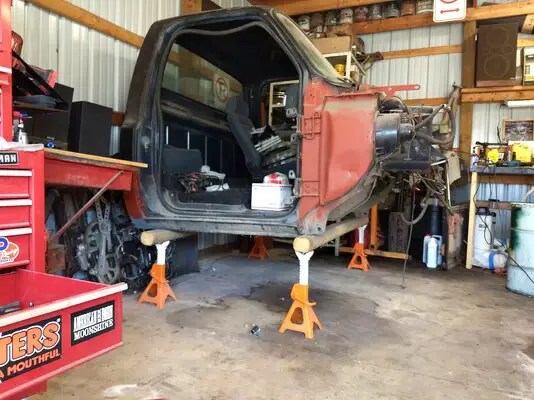
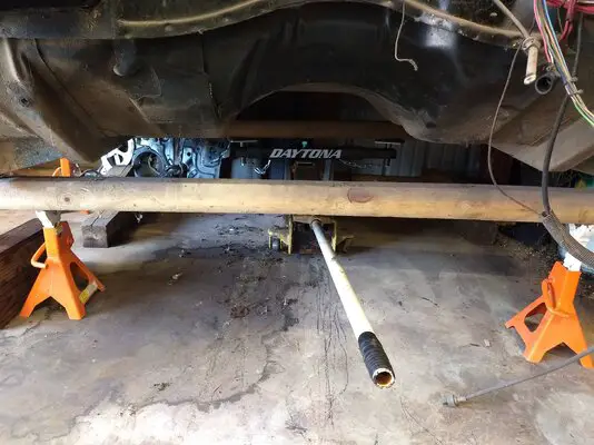
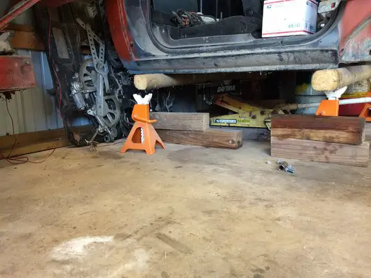
The ol' Daytona made another appearance today:

IMG_20250312_140112051.jpgIMG_20250312_140149902.jpgIMG_20250312_142214037.jpg

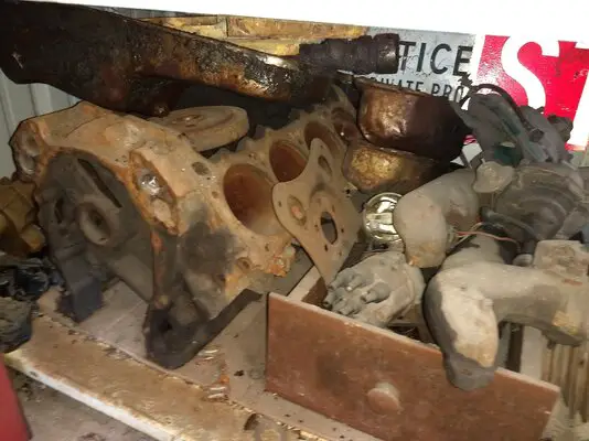
The aforementioned 383:

IMG_20250312_142238077.jpg

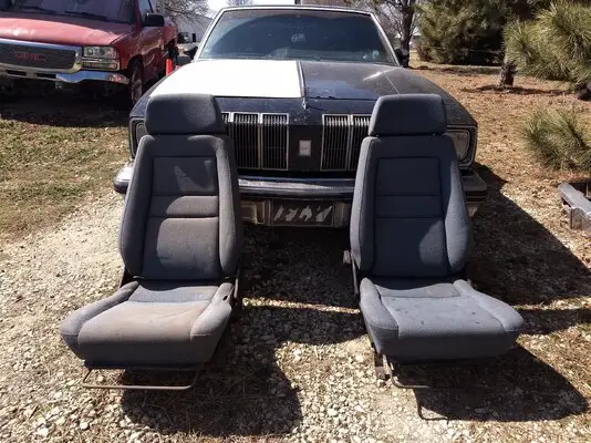
And I pulled the Recaros from the cab to put into the Cutlass. My dog tracked a melting tire plug all over one but they'll be getting dyed black anyway. They're swapped side to side here:

IMG_20250312_143853461.jpg

No G Bodies were touched today so it's not a G Body project yet.
 
OK so you are using it as I was thinking you ought to. But I would put the switch on either the relay coil power or ground myself.
Not a bad thought either way. I do plan to tap into the lead from the key switch to the HEI coil pak for continuous power and that half of the wiring is about ready to lay in but the ground lead from the relay has yet to find a home so it is open to being extended and having a toggle switch grafted into it; I even have an orphan hole in the dash that could be repurposed to hold that switch LOL the same switch that it used to have in it in the first place.


Nick
 
Filled it with the moldy drywall to take to the dump tomorrow. Got a pile of parts I wanna toss on it, but garage comes first. Then regal, then truck. Regal just needs the new 6x9s installed and interior put back together. Garage needs walls finished and ceiling done. Electrician said specifically romex just has to have 12" of cover of a solid material. So osb is plenty good for that.
20250305_003518.jpg
 
Took the GTO to meet some friends for dinner, ended up being the 7th wheel. Went out in rush hour traffic and man are people terrible drivers, love taking this car cause I can get up and go much quicker in it and take hard corners without rolling out of my seat like I do in the Monte. My one buddy brought his Viper while the other brought his Malibu, our buddy with the Lambo decided to bring the Subaru instead....
1741959932080.jpeg
1741959944876.jpeg
 
So today's plan was to post the pictures of the harness that I made for the ground wire on the relay to permit a toggle kill switch to be added; only my computer is in a snit about my camera and doesn't want to accept picture uploads. The issue is with an MS update that totally buggered the camera software that Nikon provided with the camera and now Nikon is being ornery about updating the software for compatibility. Times like this I have a profound urge to take a hammer and find a nail........................

But in this case, I went out and laid in the harness to test fit it for location and length. It seems to want to be where I want to put it so...................

DSCN4460.JPG


And this is what I came up with for a harness and switch kit.


DSCN4462.JPG


The business ends of the harness. The ring end goes directly to the ground terminal on the battery. It is a modified 12-10 crimp on wire end that I carefully reamed out to a larger diameter to fit the ground stud on the battery, It was then both crimped onto the wire and a lick of solder added for good measure.

The other terminal is a spade female that is made specifically for installation into sockets and plugs. Not visible in this picture is a stubby tang that protrudes from the back side and which is captured by a finger inside which ever pocket in the socket is about to be its destination. The big fat secret to these terminal ends is that they can be extracted using a metri-pack terminal picking tool. There is provision made in the socket for the tool to slip in along side the terminal end and depress that tang so that the terminal end can be removed and a replacement plugged in, meaning that if you damage the terminal or break off the wire you are not facing a complete change out of the socket; great for things like headlight plugs.


DSCN4463.JPG


Surprise!! Originally I just had had it in mind to run the ground lead to a ground and leave it at that. The installation instruction for the Innovate AFR gauge are pretty picky and specific about where they want the ground to go to ground, namely directly to the neg terminal on the battery. Meh, would have been easier to grab a hole in one of the heads that wasn't being used for anything else and anchor the ground there with a ring end and bolt. However............................

Back a page or so, when I posted what I was about with this AFR business I got a response from Supercharged 111 that came with an idea that I had not thought about. Summarily, why not install a switch in the ground lead so that the AFR could be "Shut Off" if necessary while everything continued on as was. I liked that idea because it seemed that the way Innovate wanted the whole harness assembled would mean that the O2 Sensor would always be hot or active as soon as you keyed the starter switch. If you needed to have the key in the run position for troubleshooting something, that would mean the sensor would be looking for input from an engine that wasn't running. Probably not a big deal but absent any knowledge on the good, the bad, and the ugly of having that circuit hot without doing anything does make a body wonder WTF might be the result

Since there did happen to be a hole already drilled in the lower dash skirt and of a proper size for a switch to be inserted, all I needed was that switch, since the original occupant had turned sideways and vanished, and enough ground wire that I could make a detour through a handy hole in firewall, to get to the dash, make the connections, stuff the switch into the hole and run a ring nut down onto the shoulder to lock it down.

For the curious who are wondering which black wire is which, I did choose to tag the black wire from the relay socket to the switch with a turn of green masking tape= power into the switch. Power out, from the switch to the Neg or ground stud on the battery remained unadorned black. And yes I did use a multi-meter to make sure that i had correctly distinguished one black wire from the other. 😉

So, some progress at last. Supposedly I have 12 ga brown primary wire on track to arrive tomorrow; that being my fall back color to use with the coil lead to create the switched side of the relay. Pink!!! is the default color and the factory wiring diagram clearly shows the coil lead to be so. My coil lead is so washed out and color bleached from many years of taking care of business that it is almost white. Thing here is that I can score 12 ga Pink primary wire, only thing here being that am I going to be that OCD about matching the wiring colors so that the whole installation looks neat and professional?????? Or am I going to go straight to get 'er done mode and just finish the whole debacle?


Nick
 
Last edited:
  • Like
Reactions: Slowpoke
Started a bathroom demo yesterday.

PXL_20250315_003423097.MP.jpg

PXL_20250315_003405081.MP.jpg


Goong after the last 2 walls today then the subfloor comes up. The toilet had been leaking and maybe the sink too? It's all under the subfloor and only 1 way to find out. I just hope I don't miss a step in the process.

RzUp.gif


Dump's not open again until Monday, I should have a few loads ready to go by then. And maybe a way ahead. Debating on what to do for a tub and/or shower with the weird ceiling.
 

GBodyForum is a participant in the Amazon Services LLC Associates Program, an affiliate advertising program designed to provide a means for sites to earn advertising fees by advertising and linking to amazon.com. Amazon, the Amazon logo, AmazonSupply, and the AmazonSupply logo are trademarks of Amazon.com, Inc. or its affiliates.

Please support GBodyForum Sponsors

Classic Truck Consoles Dixie Restoration Depot UMI Performance

Contact [email protected] for info on becoming a sponsor