What did you do to your non-G Body project today [2024 edition]

Sorry to hear that CK80, had hoped that this would not be the case. Any chance one or both of them can be rebuilt or was the damage too severe to come back from?

Ugly1, Canada Post, the Canadian federal mail delivery agency is not too bad, it is the exchange of mail over the border between USPS and CP that is the monkey wrench in the gears. Both sides have customs and import laws that are not synchronized in many ways. The biggest hurdle is security, both your Homeland Security and our CSIS. They get paid the $$$$ to be curious and that is a lot of incentive to take one's time about performing a job. It isn't called Bureaucrap for nothing, y'know. The other thing is that my indie can access vendors that I can't; they don't deal directly with end users, you have to be a retailer and have the paperwork available for scrutiny and file to prove it.
 
  • Sad
Reactions: Ugly1
Sorry to hear that CK80, had hoped that this would not be the case. Any chance one or both of them can be rebuilt or was the damage too severe to come back from?

Ugly1, Canada Post, the Canadian federal mail delivery agency is not too bad, it is the exchange of mail over the border between USPS and CP that is the monkey wrench in the gears. Both sides have customs and import laws that are not synchronized in many ways. The biggest hurdle is security, both your Homeland Security and our CSIS. They get paid the $$$$ to be curious and that is a lot of incentive to take one's time about performing a job. It isn't called Bureaucrap for nothing, y'know. The other thing is that my indie can access vendors that I can't; they don't deal directly with end users, you have to be a retailer and have the paperwork available for scrutiny and file to prove it.
A couple of acronyms come to mind, but the little guy always seems to get the worst out of it.
 
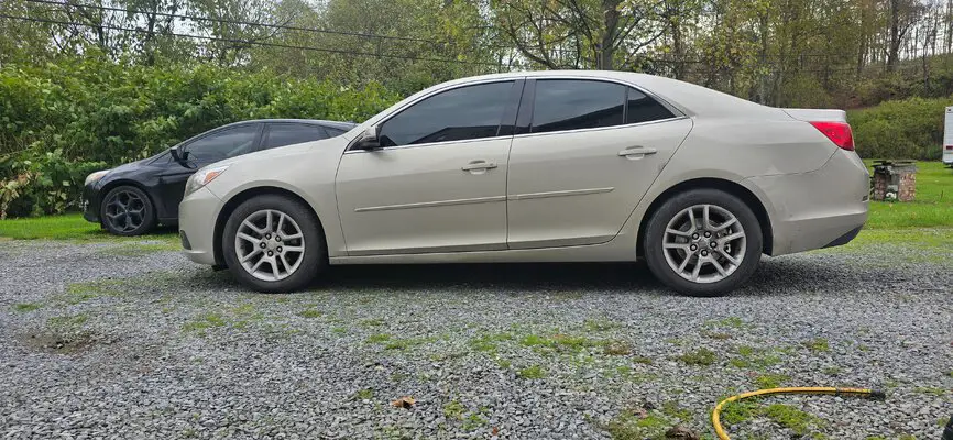
Did' a brake job on Toyota' sedan...,pedal pulsation gone but: ....found out the half of the cradle was rusted away the pully end of cradle. The motor was holding because the upper part of the cradle is bolted to the aprin the little boxed section," advised lady to sell the vehicle as she's always flipping..bled brakes as abs light was on.....que Serah" serah"
 
Sorry to hear that CK80, had hoped that this would not be the case. Any chance one or both of them can be rebuilt or was the damage too severe to come back from?

Ugly1, Canada Post, the Canadian federal mail delivery agency is not too bad, it is the exchange of mail over the border between USPS and CP that is the monkey wrench in the gears. Both sides have customs and import laws that are not synchronized in many ways. The biggest hurdle is security, both your Homeland Security and our CSIS. They get paid the $$$$ to be curious and that is a lot of incentive to take one's time about performing a job. It isn't called Bureaucrap for nothing, y'know. The other thing is that my indie can access vendors that I can't; they don't deal directly with end users, you have to be a retailer and have the paperwork available for scrutiny and file to prove it.
No sir, they're pretty well done for. The '14 took a hit through the hood and into the motor of a trunk. The '16 got what I call a 'main limb' in the form of a 10" thick sweetgum branch where the trunk divided itself into 3 sections as it grew, well that took out the roof, trunk, and hood, with all the water damage to the interior, dash, and wiring that comes with it.

If the buyback is cheap enough I'll salvage the drivetrain and doors off the '16, but, car has 160k on it so it'll have to be cheap to be worth it. The '14 I'll buy and just park as parts in the warehouse. Interior was mint being under 20k miles, and, the firewall back was in decent shape. But the front frame rails, strut towers, all that stuff got bent up so it'd be a healthy chunk of work, plus needing an engine, and front clip, to make it into a car again.
 
Fiance wanted a set of steps and a gate for trick or treaters this year so I made one out of half repurposed stuff and some hardware store stuff. I'm a car guy not a wood and house repair guy, but it works.
Yes, the steps are sitting on bricks. No I don't care. The ones on the rear of the house done by the "professionals" who "remodeled" this place are just sitting in dirt.
orca-image-1487605402~2.jpeg

20241013_002641.jpg
20241013_002516.jpg

Not quite done trim wise but it works. Next is to fix some rotten deck boards. Yep, that's what 160k buys you nowadays. Uneven walls floors, walls not attached to floors (floating pretty much), rotten decks, garage with power and fuse box crudely installed, then ripped out, broken washer drain pipes, etc.
 
As most of the lurkees around here can attest, I am not a one-project-at-a-time person; it's a common situation for many of us and I can think of a few hereabouts who have more projects on the go than fingers on a hand.

So I have what I call "In between" projects as, in between one major thing to do and another. There are smaller or easier sub projects or items to do or accomplish on the build list that get fitted into the schedule as needed or as time permits. Since I am on hold for the long weekend up here due to a no show in the body metal department, I elected to be productive by trying to advance a m/c floorboard project that I have been working on periodically.


DSCN4399.JPG


DSCN4400.JPG


Going to go about this slightly backwards, starting with the result and the application and working back to how I ended up with what I needed

What you see is a mounting block for a motorcycle foot peg that has been adapted for use on a mini-floorboard. To make the adaptation work, I had to fabricate custom length spacers to use on either side of the block to both center it and to make it fit snugly enough that there would be no pressure or tension imparted to the mounting ears on the floorboard itself.


DSCN4402.JPG


For my raw material, I chose 5/8th steel shaft. The choice of OD was not random. The peg itself is 5/8ths square bar and it came that way from the manufacturer. Just recently I was able to score a second, brand new, pair of these pegs and might swap out the older ones for the nicer ones. Chroming for these is not an option at this point; too expensive when they can be bought already chromed and too hard, as I have noted elsewhere, to find a chromer that is still in business and can produce a quality product at a decent price. It is also, strictly speaking, not really necessary as to see these pegs you would pretty much have to be flat on your back and looking up. Only three ways that I know of to get that way, One, being that you are working on the bike, two, that you are curious and wanted a closer look, and three, that you decided to prove the all the allegations of your stupidity that have been circulating around and stepped off the curb when the light was red.

Once I had found that I, in fact, had the correct size of shaft in stock, (BIG SURPRISE!!!!!) it was time to get out the technology.


DSCN4403.JPG


It definitely helps to have a lathe available for minor whittling jobs that come up from time to time. With the shaft locked into the lathe chuck, the first step was to face both ends of the shaft to get them flat and square to the outer surface of the shaft itself. Once that was accomplished, the next step was to machine a centre divot using a centering drill. They come in various dimensions and are just to create the machinist equivalent of a center punch mark in the exact center of the shaft so that any tool to be used that follows will track the mark instead of wandering away and wreaking havoc.

Once the live center was established, I then gun drilled the shaft, starting with an 11/64 pilot bit, and then moving up to a 1/4 inch finishing pass. The goal for the drilling was to reach a deep enough ID for the spacers that I could then just cut off blanks from the main piece and face/shave them down to the correct thickness. As it was, with two "test" pieces that consumed material along the way, I did have to revisit the drilling portion of the job and deepen the hole another inch. For that I just went with the final hole size bit as I had enough hole still present in the shaft that it would act as a guide to the bit so it wouldn't wander.


DSCN4404.JPG


After all that high tech prep work, the next step was decidedly very low brow. Into the vice and wail on it with a hacksaw. In measuring out for the blanks, I had gone very generous on the basic rough thickness measurement, being fairly certain from past experience that the hacksaw would cut anything but straight and true. Which was pretty much what happened. No pictures of the actual face down to show; kind of was concentrating on getting the spacers to be faced flat while not taking too much at that point. The objective was to get to a starting point with each spacer and then carefully shave them down a few thou at a time to sneak up to the final thickness. That proved to be .361, +/_ .0005, or somewhere short of 3/8th inch and likely closer to 11/32". What that thickness gave me was a close to zero-zero fit that let me slip everything into place on the 1/4 inch crossbolt but left nothing for clearance or tolerance. Again, the goal for the spacers was to make them as thick as possible, as close to exactly alike as possible, and end up with them as tight as possible so the the floor board would articulate up/down on the peg but not flop or wobble, even with the cross bolt still loose. Hey, Me here being picky, picky, picky, based on need and necessity; Fuggedaboudit.


DSCN4405.JPG


DSCN4407.JPG


A couple of side by sides of what I started with and what/where I ended up with. That dimple in the end of the shaft stump is the bottom of the gun drilled hole. Although my estimate for allout depth of the hole in the shaft that I would have to drill was sketchy at best, by a combination of blind luck and pure happenstance it actually did prove to be enough at the end. As noted above, I did have to add a little more depth to the original estimate due to a couple of "test spacers" happening during the overall cut/machine process, yet I still came that close to being dead nuts for depth at the end. How close? Well, when I cut the last spacer blank and set it into the lathe chuck to face it, I thought that I might have to visit the hole in it jic. So I rehung the drill chuck and and bit assembly into the tail stock and slipped them into position only to discover that the bit slid through without issue. Go figure.


DSCN4412.JPG


And the objective of all this labor and effort? What you see above. As the two .361's had already been slipped into position and the bolt hung to hold them and the peg, these are my stand ins for this shot; that's right, the two "test spacers" that I alluded to before. They disqualified themselve by being too short after being faced. The hacksaw cut to remove them from the shaft had walked too much away from square and finally cost me the correct width at the end by time I had them shaved down to flat and then went for the actual needed width. You can't actually tell for size but the one is .355 and the other is shorter still. .006 might not seem all that much but times two, due to needing two spacers, and it can be felt when you assemble the peg to its tabs. To get to tight on the nut would have put too much stress on those mounting ears that you can see in the first picture. So these will be set aside and binned against future need. Waste not; want not.

The next step for this project is to establish exactly where I want these floorboards to land on the new mounting strap. That, right now, is attached to the bike, and there it will remain as I will be fitting to it as it sits, rather than trying to fit it to the floor board away from the ride. Not complicated but some fuzzy thinking going on right now so...............................................As always, JUst me,


CopperNick
 
"Sub projects" I like that 🤣
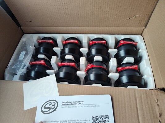
Road trip to summit racing yesterday picked up set of S&B body mounts and some heat wrap for my 09 Chevy 2500
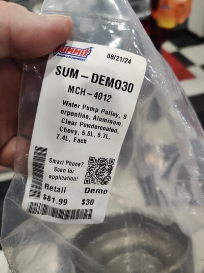
Also scored a March water pump pulley that work for my MK6 BBC accessories drive
Hope to have my dmax moving by thanksgiving
 

Attachments

  • IMG_20241012_182931552.jpg
    IMG_20241012_182931552.jpg
    1.7 MB · Views: 12
  • IMG_20241012_171614133.jpg
    IMG_20241012_171614133.jpg
    1.2 MB · Views: 14
So things escalated quickly this past week. I started on the alternator for my daily focus. I get a call from my son that his car is making a grinding noise from the rear when he hits the brake. We all know most likely what it is. Just a matter of how much damage was done.

So i stayed up late getting the alt and battery into the focus so i would have room for his car. Drove the focus to work the next day and it still has the hard start issue. That can be a problem i revisit another day. Its out of the garage for now.

20241013_115852.jpg

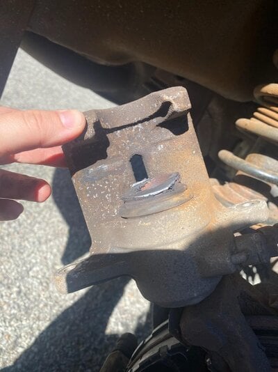
Pulled his car in the next night to find the expected chewed up pad and rotor on his car. Looked as though the caliper was hanging up. After talking with him, he was fine getting new pads, rotors, and calipers for the rear. Ordered parts and waited. Put his car outside and he borrowed my truck to use for work.

20241013_115619.jpg

Then started car rodeo to get the elky back into the big garage for its upcoming work. Then my daughter calls and tells me that her boyfriends car is making noise from the rear. They tried to change the pads and found a bad caliper.

IMG_0826.jpg

So had them order pads, rotor, and caliper.

My sons parts showed up yesterday. Fixed his last night. Test drove it and realized he had a headlight out. Ran to mal wart last night got bulbs. Fixed that this mourning.

Have to wait on parts for my daughters boyfriends car. That will get done maybe next sunday depending on schedules.

Now to get my sons car back to him so i can get my truck back. I need it and my trailer to do a run for pagrunt ( i didnt forget! ).

Back on night shift this week again. I'll work on the elky.......someday! Oh yeah and i have four vehicles here to get through state inspection.

Geesh!
 
As most of the lurkees around here can attest, I am not a one-project-at-a-time person; it's a common situation for many of us and I can think of a few hereabouts who have more projects on the go than fingers on a hand.

So I have what I call "In between" projects as, in between one major thing to do and another. There are smaller or easier sub projects or items to do or accomplish on the build list that get fitted into the schedule as needed or as time permits. Since I am on hold for the long weekend up here due to a no show in the body metal department, I elected to be productive by trying to advance a m/c floorboard project that I have been working on periodically.


View attachment 247332


View attachment 247333


Going to go about this slightly backwards, starting with the result and the application and working back to how I ended up with what I needed

What you see is a mounting block for a motorcycle foot peg that has been adapted for use on a mini-floorboard. To make the adaptation work, I had to fabricate custom length spacers to use on either side of the block to both center it and to make it fit snugly enough that there would be no pressure or tension imparted to the mounting ears on the floorboard itself.


View attachment 247334


For my raw material, I chose 5/8th steel shaft. The choice of OD was not random. The peg itself is 5/8ths square bar and it came that way from the manufacturer. Just recently I was able to score a second, brand new, pair of these pegs and might swap out the older ones for the nicer ones. Chroming for these is not an option at this point; too expensive when they can be bought already chromed and too hard, as I have noted elsewhere, to find a chromer that is still in business and can produce a quality product at a decent price. It is also, strictly speaking, not really necessary as to see these pegs you would pretty much have to be flat on your back and looking up. Only three ways that I know of to get that way, One, being that you are working on the bike, two, that you are curious and wanted a closer look, and three, that you decided to prove the all the allegations of your stupidity that have been circulating around and stepped off the curb when the light was red.

Once I had found that I, in fact, had the correct size of shaft in stock, (BIG SURPRISE!!!!!) it was time to get out the technology.


View attachment 247335


It definitely helps to have a lathe available for minor whittling jobs that come up from time to time. With the shaft locked into the lathe chuck, the first step was to face both ends of the shaft to get them flat and square to the outer surface of the shaft itself. Once that was accomplished, the next step was to machine a centre divot using a centering drill. They come in various dimensions and are just to create the machinist equivalent of a center punch mark in the exact center of the shaft so that any tool to be used that follows will track the mark instead of wandering away and wreaking havoc.

Once the live center was established, I then gun drilled the shaft, starting with an 11/64 pilot bit, and then moving up to a 1/4 inch finishing pass. The goal for the drilling was to reach a deep enough ID for the spacers that I could then just cut off blanks from the main piece and face/shave them down to the correct thickness. As it was, with two "test" pieces that consumed material along the way, I did have to revisit the drilling portion of the job and deepen the hole another inch. For that I just went with the final hole size bit as I had enough hole still present in the shaft that it would act as a guide to the bit so it wouldn't wander.


View attachment 247336


After all that high tech prep work, the next step was decidedly very low brow. Into the vice and wail on it with a hacksaw. In measuring out for the blanks, I had gone very generous on the basic rough thickness measurement, being fairly certain from past experience that the hacksaw would cut anything but straight and true. Which was pretty much what happened. No pictures of the actual face down to show; kind of was concentrating on getting the spacers to be faced flat while not taking too much at that point. The objective was to get to a starting point with each spacer and then carefully shave them down a few thou at a time to sneak up to the final thickness. That proved to be .361, +/_ .0005, or somewhere short of 3/8th inch and likely closer to 11/32". What that thickness gave me was a close to zero-zero fit that let me slip everything into place on the 1/4 inch crossbolt but left nothing for clearance or tolerance. Again, the goal for the spacers was to make them as thick as possible, as close to exactly alike as possible, and end up with them as tight as possible so the the floor board would articulate up/down on the peg but not flop or wobble, even with the cross bolt still loose. Hey, Me here being picky, picky, picky, based on need and necessity; Fuggedaboudit.


View attachment 247337


View attachment 247338


A couple of side by sides of what I started with and what/where I ended up with. That dimple in the end of the shaft stump is the bottom of the gun drilled hole. Although my estimate for allout depth of the hole in the shaft that I would have to drill was sketchy at best, by a combination of blind luck and pure happenstance it actually did prove to be enough at the end. As noted above, I did have to add a little more depth to the original estimate due to a couple of "test spacers" happening during the overall cut/machine process, yet I still came that close to being dead nuts for depth at the end. How close? Well, when I cut the last spacer blank and set it into the lathe chuck to face it, I thought that I might have to visit the hole in it jic. So I rehung the drill chuck and and bit assembly into the tail stock and slipped them into position only to discover that the bit slid through without issue. Go figure.


View attachment 247339


And the objective of all this labor and effort? What you see above. As the two .361's had already been slipped into position and the bolt hung to hold them and the peg, these are my stand ins for this shot; that's right, the two "test spacers" that I alluded to before. They disqualified themselve by being too short after being faced. The hacksaw cut to remove them from the shaft had walked too much away from square and finally cost me the correct width at the end by time I had them shaved down to flat and then went for the actual needed width. You can't actually tell for size but the one is .355 and the other is shorter still. .006 might not seem all that much but times two, due to needing two spacers, and it can be felt when you assemble the peg to its tabs. To get to tight on the nut would have put too much stress on those mounting ears that you can see in the first picture. So these will be set aside and binned against future need. Waste not; want not.

The next step for this project is to establish exactly where I want these floorboards to land on the new mounting strap. That, right now, is attached to the bike, and there it will remain as I will be fitting to it as it sits, rather than trying to fit it to the floor board away from the ride. Not complicated but some fuzzy thinking going on right now so...............................................As always, JUst me,


CopperNick
Just had a painfully brilliant moment. If I remember correctly they make a paint that looks and acts like chrome. You’d have to look into it and it was a few years ago I saw it.
 

GBodyForum is a participant in the Amazon Services LLC Associates Program, an affiliate advertising program designed to provide a means for sites to earn advertising fees by advertising and linking to amazon.com. Amazon, the Amazon logo, AmazonSupply, and the AmazonSupply logo are trademarks of Amazon.com, Inc. or its affiliates.

Please support GBodyForum Sponsors

Classic Truck Consoles Dixie Restoration Depot UMI Performance

Contact [email protected] for info on becoming a sponsor