BUILD THREAD my 1980 Grand Prix w/BBC 454 build thread
- Thread starter 454GrandPrix
- Start date
You are using an out of date browser. It may not display this or other websites correctly.
You should upgrade or use an alternative browser.
You should upgrade or use an alternative browser.
- Status
- Not open for further replies.
I put a lot of thought into that, too. In the end, I decided the shorter stroke would be beneficial for longevity at higher RPM... so I stayed with the 4.0" crank.
That is why you would need to go with at least a .250 longer rod with the added stroke.
My 565 BBC is a 9.78 deck with 4.25 stroke, 4.60 bore and I run a 6.535 rod (.400 longer than stock) and I shift at 7400 and it pulls past 7600, my rod ratio is 1.537 which is better than a stock 454 or 502.
And by the way my very first Gbody was a 78' Grand Prix which is where it all started.
Last edited:
I like those stock valve covers. Are you going to paint them engine color or leave them black?
Mike wanted me to paint them to match the engine, but I prefer the contrast. I'll leave them black.
My 565 BBC is ...
Wow, just... wow. Any dyno figures or timeslips for that monster?
When I bought the car, the speedometer wasn't working. I removed the main cluster to see if the cable was turning, but it was not. Too lazy to crawl under the car and check it at the transmission end, I instead dug up my old iPhone4--it has the Dashboard app that gives a real-time GPS speed readout. Every time I started the car, I'd pull the phone out of the glovebox, fire it up, open the app, and prop it on the dash to serve as my speedometer. Sure, it was redneck in a high tech sort of way... but it worked for a while.
Something had to be done. Since my car didn't come with the secondary gauges but just had warning lights, I knew my long-term plan was to install a full set of AutoMeter gauges in the car. I considered an electric speedometer, but at the time I was planning to run a carburetor so I wasn't sure how I'd hook it up. But then I discovered AutoMeter's GPS speedo, and--better yet--I found it on sale at Summit Racing. So I ordered that.
Now I got to open up my main cluster and start carving it like a Thanksgiving Day turkey.

I stole an idea from BangShift and bought a rubber plumbing coupler at Home Depot. I trimmed off one end, inserted it into my cluster cover speedometer hole, and then squoze the speedo into place. It was a perfect fit. I made a small wiring harness with a fancy connector to facilitate future cluster removals, then tried it out in the car.
(Sorry--this picture is a bit blurry from blitzing along at 36 MPH.)

Tah-dah! It worked. I continued to drive the car like this for a couple months.
Something had to be done. Since my car didn't come with the secondary gauges but just had warning lights, I knew my long-term plan was to install a full set of AutoMeter gauges in the car. I considered an electric speedometer, but at the time I was planning to run a carburetor so I wasn't sure how I'd hook it up. But then I discovered AutoMeter's GPS speedo, and--better yet--I found it on sale at Summit Racing. So I ordered that.
Now I got to open up my main cluster and start carving it like a Thanksgiving Day turkey.

I stole an idea from BangShift and bought a rubber plumbing coupler at Home Depot. I trimmed off one end, inserted it into my cluster cover speedometer hole, and then squoze the speedo into place. It was a perfect fit. I made a small wiring harness with a fancy connector to facilitate future cluster removals, then tried it out in the car.
(Sorry--this picture is a bit blurry from blitzing along at 36 MPH.)

Tah-dah! It worked. I continued to drive the car like this for a couple months.
As you could guess, it didn't take me very long to get tired of the warning lights. I went ahead and ordered a quartet of matching 2 1/16" gauges to install in the secondary cluster. This installation process was fairly similar to when I installed the speedometer, although I didn't need any rubber spacer to mount these gauges. In fact, I used my dremel to very gently enlarge the holes to make it easier for the gauges to slip into place. As before, I built a wiring harness complete with some connectors to facilitate removing this cluster in the future.
Now that those gauges were in place, it looked dumb to have a gaping hole where the tachometer should reside. So, of course, I bought the matching tach and installed it. I grafted its wiring connections into the speedometer's harness and that was that.
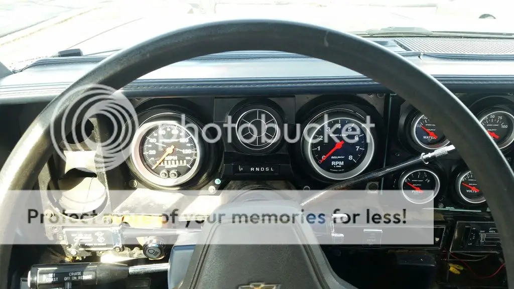
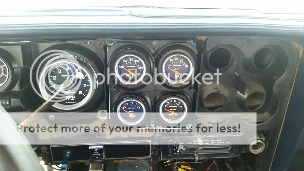
I took out the car's coolant temperature switch and replaced it with the temp sensor that came with the gauge. The fuel gauge used the stock wiring, and the voltage gauge is a no-brainer. The oil pressure gauge needs a sensor like the temperature gauge, but I couldn't find the OEM pressure switch on the engine. (I think it's tucked up above the oil filter, behind some accessory brackets.) Oh, well; I decided I would just wait to install that sensor with the V8 engine. Besides, three out of four functional secondary gauges is two more than I had before I started this upgrade. 😉
The tachometer was a similar situation. My car didn't have the OEM tach wire going through the firewall. I did run one to the engine bay, but I didn't have the special plug to attach it to the distributor itself. Oh, well, I figured that could also wait for the V8 install.
At this point, I decided that everything looks pretty now... except for one problem: I have to look at all those gauges through the horrific green 15" Chevrolet steering wheel. On a day off, Mike and I hit the local Pick 'N Pull to scout out a suitable replacement. I was wanting something of a slightly smaller diameter which was period correct (more or less) and, hopefully, a Pontiac design. My dream seering wheel would have been from a late '70s Trans Am, but of course no such vehicle was there. However, there was an '86 Fiero GT in the yard... and its gray 4-spoke steering wheel was in perfect condition. The Fiero logo is kinda reminiscent of the Firebird logo (if you don't look too closely), so I decided it would do very nicely.


Now I just need to figure out why my horns don't work.
Now that those gauges were in place, it looked dumb to have a gaping hole where the tachometer should reside. So, of course, I bought the matching tach and installed it. I grafted its wiring connections into the speedometer's harness and that was that.


I took out the car's coolant temperature switch and replaced it with the temp sensor that came with the gauge. The fuel gauge used the stock wiring, and the voltage gauge is a no-brainer. The oil pressure gauge needs a sensor like the temperature gauge, but I couldn't find the OEM pressure switch on the engine. (I think it's tucked up above the oil filter, behind some accessory brackets.) Oh, well; I decided I would just wait to install that sensor with the V8 engine. Besides, three out of four functional secondary gauges is two more than I had before I started this upgrade. 😉
The tachometer was a similar situation. My car didn't have the OEM tach wire going through the firewall. I did run one to the engine bay, but I didn't have the special plug to attach it to the distributor itself. Oh, well, I figured that could also wait for the V8 install.
At this point, I decided that everything looks pretty now... except for one problem: I have to look at all those gauges through the horrific green 15" Chevrolet steering wheel. On a day off, Mike and I hit the local Pick 'N Pull to scout out a suitable replacement. I was wanting something of a slightly smaller diameter which was period correct (more or less) and, hopefully, a Pontiac design. My dream seering wheel would have been from a late '70s Trans Am, but of course no such vehicle was there. However, there was an '86 Fiero GT in the yard... and its gray 4-spoke steering wheel was in perfect condition. The Fiero logo is kinda reminiscent of the Firebird logo (if you don't look too closely), so I decided it would do very nicely.


Now I just need to figure out why my horns don't work.
Last edited:
You have to love the GP dash for it's easy layout to install aftermarket gauges.
For your tach wire you can temporarily put a female spade terminal on the end and then plug it into your HEI cap.
And I can't believe you didn't want to keep that awesome chained steering wheel in there.
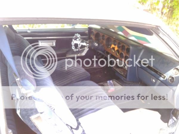
For your tach wire you can temporarily put a female spade terminal on the end and then plug it into your HEI cap.
And I can't believe you didn't want to keep that awesome chained steering wheel in there.

Back when I decided to install the electric radiator fan, I obviously needed a way to control it. Again thinking my long-term setup would involve a carburetor--in other words, no ECU--I figured I'd need some sort of free-standing control for the fan. I've heard of guys who install mechanical temp sensors that trigger a relay; I already had a relay, so it seemed obvious to follow their idea. I went looking around and found this 2-piece temperature sensor that triggers "on" at 210^ and "off" at 200^:

Now I just needed a place to install it. Well, hey, how about one of those radiator hose insert thingys? You know, you slice out a chunk of your hose, insert the metal piece, and then attach the fitting to the threaded hole. Sounded pretty easy, so I got one of those and installed it right next to the radiator:

As you can tell from the first photo, installation is easy--just screw in the bushing/fitting, then screw the sensor into that. How hard could it be? Well, I managed to screw it up when I accidentally exceeded the torque spec of the sensor. %$#@! There went $20 down the drain:

So I ordered another sensor. When it showed up I was about to install it... and then for some reason I suddenly decided I needed to test it for proper operation first (I didn't have the coolant temp gauge in the car yet). To look at it, you'd assume the two prongs become conductive at 210^, then they stop conducting once the temp drops below 200^. Testing them in the cold showed no continuity between anything, as expected. Since my wife wasn't home, I went inside and threw some water in a pot on the stove. I ran a string through the holes in the sensor prongs and set it in the water.

Once it was at a strong boil--meaning it was obviously over 210^--I again tested for continuity. Nothing. I checked everything I could think of--between the two terminals, between terminal A and the body, between terminal B and the body. Nada. What gives?? I even tried contacting the seller, but there was a (ahem) "cultural gap" and they were unable to help me in any way.
Out of desperation, I then abandoned the sensor idea and just mounted a simple toggle switch on the dash next to my rear defroster switch. Now I could feed a ground signal to my relay whenever I wanted (which was pretty much whenever I drove the car) and thus keep the temperature in check. I've been driving it like this ever since.
On the plus side, once the engine is broken in and I switch over to my FiTech EFI, I can control the fan that way.

Now I just needed a place to install it. Well, hey, how about one of those radiator hose insert thingys? You know, you slice out a chunk of your hose, insert the metal piece, and then attach the fitting to the threaded hole. Sounded pretty easy, so I got one of those and installed it right next to the radiator:

As you can tell from the first photo, installation is easy--just screw in the bushing/fitting, then screw the sensor into that. How hard could it be? Well, I managed to screw it up when I accidentally exceeded the torque spec of the sensor. %$#@! There went $20 down the drain:

So I ordered another sensor. When it showed up I was about to install it... and then for some reason I suddenly decided I needed to test it for proper operation first (I didn't have the coolant temp gauge in the car yet). To look at it, you'd assume the two prongs become conductive at 210^, then they stop conducting once the temp drops below 200^. Testing them in the cold showed no continuity between anything, as expected. Since my wife wasn't home, I went inside and threw some water in a pot on the stove. I ran a string through the holes in the sensor prongs and set it in the water.

Once it was at a strong boil--meaning it was obviously over 210^--I again tested for continuity. Nothing. I checked everything I could think of--between the two terminals, between terminal A and the body, between terminal B and the body. Nada. What gives?? I even tried contacting the seller, but there was a (ahem) "cultural gap" and they were unable to help me in any way.
Out of desperation, I then abandoned the sensor idea and just mounted a simple toggle switch on the dash next to my rear defroster switch. Now I could feed a ground signal to my relay whenever I wanted (which was pretty much whenever I drove the car) and thus keep the temperature in check. I've been driving it like this ever since.
On the plus side, once the engine is broken in and I switch over to my FiTech EFI, I can control the fan that way.
Was the sensor grounded?
No, but I figure that shouldn't matter. If the sensor were grounded, that just means the housing would show continuity with one (or both) of the terminals... but it did not. (shrug)
Also you may like my "Learning Curve" build!
I went looking for it, and you're right--lots of great stuff there!
Today I spent some more time with my new engine. Just some more final preparations for dropping it in--installed new spark plugs, attached the clam shells, inserted a few plugs to seal unused passages, and properly torqued the intake manifold (including using proper thread sealant). Oh, and I installed my new thermostat and water neck. 😀
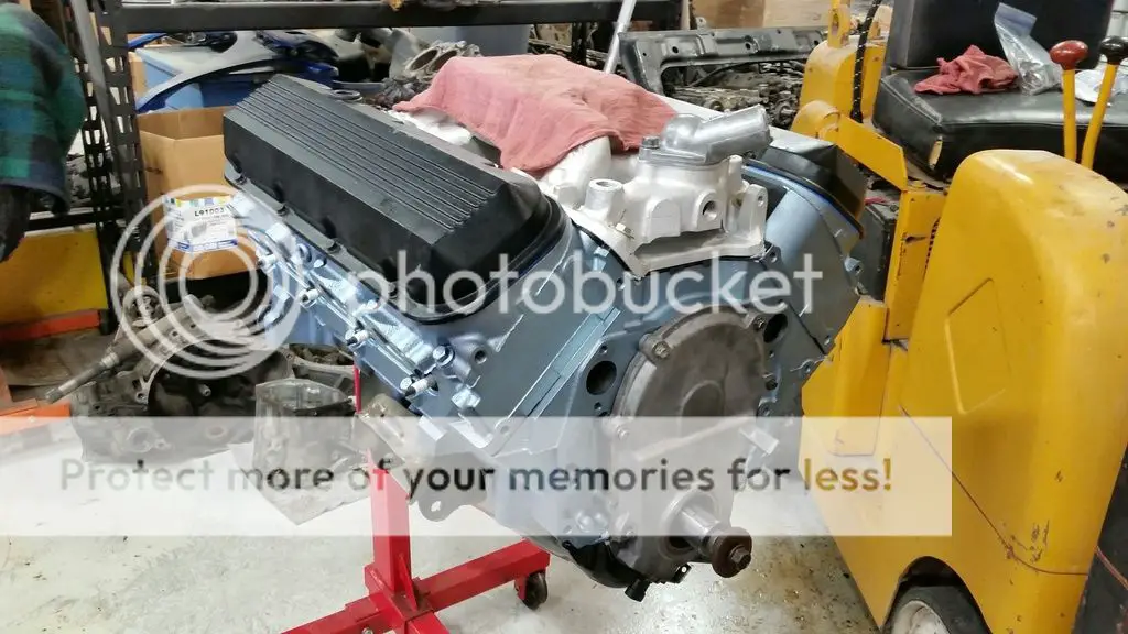
I'm just about finished until I take it off the engine stand and drop it into the car.
- Status
- Not open for further replies.
Similar threads
- Replies
- 1
- Views
- 298
- Replies
- 1
- Views
- 145
- Replies
- 2
- Views
- 115
GBodyForum is a participant in the Amazon Services LLC Associates Program, an affiliate advertising program designed to provide a means for sites to earn advertising fees by advertising and linking to amazon.com. Amazon, the Amazon logo, AmazonSupply, and the AmazonSupply logo are trademarks of Amazon.com, Inc. or its affiliates.

