What did you do to your non-G body project today? [2021]

Status
Not open for further replies.
Yo, Texas82GP. have just discovered that I have another question for your magical book. Trying to do some research on the electrical plug on that 700R4 that is connected to the t-mission on the driver's side. This is the TCC lockup and according to what little I have learned, it takes its power in on the A Terminal and you either leave it alone which means that all the gears can go into lockup on demand or you run a jumper from D to B which allows only 4th to lock up.

Right now that harness has only two wires, a light blue one and a green one. They are connnected to a VOES switch that also has a two pin male plug attached to it. Now one of those wires is power and goes, if I have this right, to a fuse or breaker terminal. The other is strange. According to what diagrams I have been able to review, that wire, whatever color it is or is supposed to be, is somehow supposed to go to the hot or power side of the brake light switch. This is confusing. Think I may have to go looking for a manual for an 85 G-10 or C/K-10 to see if it has a complete wiring diagram I can actually see and trace. My major complication here is that there are no controllers or CCC boxes in my van; it is just too old and too early for all that.

Can you ask your magic book and see What what it has to show on the subject? Thanks.


Nick
TCC was controlled by the ECM. In the absence of an ECM to control TCC lockup, I'd think you'd need an aftermarket lockup control kit. Do these help?
20210622_190911_copy_1134x2016.jpg
20210622_190943_copy_1134x2016.jpg
20210622_190851_copy_1134x2016.jpg
 
  • Like
  • Informative
Reactions: 5spdCab and Rktpwrd
Yo, Texas82GP. have just discovered that I have another question for your magical book. Trying to do some research on the electrical plug on that 700R4 that is connected to the t-mission on the driver's side. This is the TCC lockup and according to what little I have learned, it takes its power in on the A Terminal and you either leave it alone which means that all the gears can go into lockup on demand or you run a jumper from D to B which allows only 4th to lock up.

Right now that harness has only two wires, a light blue one and a green one. They are connnected to a VOES switch that also has a two pin male plug attached to it. Now one of those wires is power and goes, if I have this right, to a fuse or breaker terminal. The other is strange. According to what diagrams I have been able to review, that wire, whatever color it is or is supposed to be, is somehow supposed to go to the hot or power side of the brake light switch. This is confusing. Think I may have to go looking for a manual for an 85 G-10 or C/K-10 to see if it has a complete wiring diagram I can actually see and trace. My major complication here is that there are no controllers or CCC boxes in my van; it is just too old and too early for all that.

Can you ask your magic book and see What what it has to show on the subject? Thanks.


Nick
FWIW - those early 700s were ecm optional. In the case of the C/K series truck, there was no ecm until 1987.

That means absent a swap/conversion, a 1986-down truck does not use a computer to control the 700 series trans.
 
FWIW - those early 700s were ecm optional. In the case of the C/K series truck, there was no ecm until 1987.

That means absent a swap/conversion, a 1986-down truck does not use a computer to control the 700 series trans.
What controlled lockup on 86 and prior trucks? Did they have something on the throttle?
 
What controlled lockup on 86 and prior trucks? Did they have something on the throttle?
Here's a wiring schematic for the circuit:

700 R4 lockup3.jpg


It works off using the brake switch plus that low vacuum firewall switch/solenoid. They will cut the power to the lock up solenoid inside the pan. transmission has 2 or 3 pressure switches plus a solenoid. Power goes fuse panel to brake switch, then firewall low vac switch, then into the trans. With hard throttle on the motor, vacuum signal briefly decreases and low vac switch breaks circuit, cuts power to the lock up circuit, then a switch inside the trans detects pressure in the 4th gear oil circuit. The brake switch is similar, if braking it cuts the power circuit, unlocks the torque converter, stays unlocked until that 4th gear pressure switch detects pressure again.

IIRC early full-sized cars used the same system, I believe it was what was in an 84 impala I had

Edit: CopperNick not sure if that'll help ya
 
Exactly So, and that is what I have in my wiring harness for this unit. I did manage to locate a sort of wiring diagram from an images site but it is not excerpted from a manual or from some other qualified source. And it only "sort of" answers where power to the Voes comes from which is a maybe/possibility that is too iffy to make me happy. All I truly know here is that applying vacuum to the Voes switch activates the flow of current into the circuit side of the harness and that goes down to the plug in. it is what happens next and/or before that is not clear.

What I did manage to do a little earlier was to visit the Faxon Literature site and learn that they had an original edition factory service manual set for the 85 Light duty Truck group which includes both the C/K series pick ups as well as the G10/20/30 and 15/25/35 Vans The Zeros were Chevs and the Fives were the GMC's. What ck80 has just confirmed for me means that I can do some kind of direct wiring addition to accommodate the Voes. I just have to confirm from where the juice would come to feed the Voes power in or +.

Thanks for all the help so far, gentlemen, It is greatly appreciated. The faster I can get this off its cribbing the faster I can return to the joys of stripping the mung and crud off my 85's differential so I can paint the floor pan back there as well as the diff and move forward on this again.


Nick
Why wait?

http://www.mediafire.com/download/9..._Light_Truck_Service_Manual_CK_10_30_Only.pdf

http://www.mediafire.com/download/m...Series_Service_Manual_1984_Revision_Pages.pdf

http://www.mediafire.com/download/v...MC_Light_Truc_Wiring_Manual_CK_10_30_Only.pdf

see if that works for ya, 1st should be manual, 2nd should be updates/revisions, 3rd is wiring
 
Just spotted your diagram and took a copy of it over to the resident software in my computer to enlarge it. Just from a cursory peek it has the correct wire colors for the harness that I have and suggests the brake switch as the power source which jibes with what I learned from elsewhere. I think that I can do something based on ck80's diagram; Thank You, Sir!! The only question left to answer is how to limit the lockup to 4th exclusively and I think this diagram may have a suggestion for that as well.

On the mechanical side of things the transmission is completely bedded in now. I added an Energy Suspension rear t-mount and then lifted the crossmember into position.

Just as a very important FYI for anyone thinking about all this, the 700R4 is not compatible with the TH350 crossmember. The 700 has a crossmember that has more offset to the rear built into it as well as a deeper drop and wider/taller mounting ears. It does line up with the older mounting points on the frame so that much didn't change. I had been warned many years ago that this might be the case and was able to score a correct part during a visit to a local pick-a-part that had an 85 sitting on stands and about to be condemned to the crusher. The transmission was junk thanks to a moron of a fork lift operator but the crossmember was scrounge-able and out it came. Hulk was gone the next time I visited; these guys were located right next door to a scrap meta crushing and shredding operation and tended not to hang on to inventory very long.

And all the rain has been good for my lawn rehab project but bad for my lungs. Just can't win here.


Nick
 
  • Like
Reactions: Texas82GP
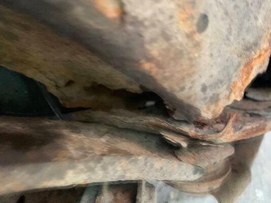
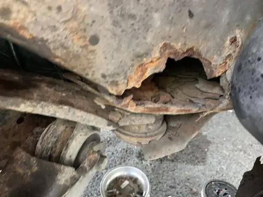
Got rid of it! Went to do rear brakes on the wife’s car and found what was left of the rear subframe. With over 200k on the clock, not worth fixing. Had it up for part out on market place Saturday night and some one came with a trailer and bought it Sunday. 2005 Ford Freestyle.
 

Attachments

  • 9A04F261-DAF8-4191-A041-7758AA25D473.jpeg
    9A04F261-DAF8-4191-A041-7758AA25D473.jpeg
    1.1 MB · Views: 93
  • 1FA8905F-5821-477C-BE0E-CEE7462FA0AA.jpeg
    1FA8905F-5821-477C-BE0E-CEE7462FA0AA.jpeg
    1.2 MB · Views: 104
Status
Not open for further replies.

GBodyForum is a participant in the Amazon Services LLC Associates Program, an affiliate advertising program designed to provide a means for sites to earn advertising fees by advertising and linking to amazon.com. Amazon, the Amazon logo, AmazonSupply, and the AmazonSupply logo are trademarks of Amazon.com, Inc. or its affiliates.

Please support GBodyForum Sponsors

Classic Truck Consoles Dixie Restoration Depot UMI Performance

Contact [email protected] for info on becoming a sponsor