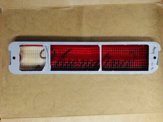
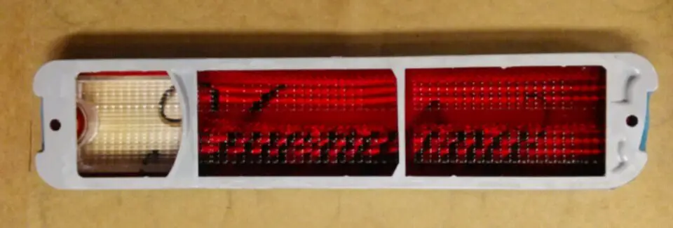
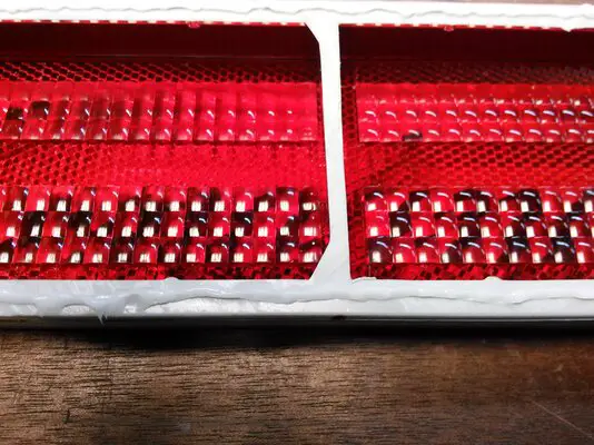
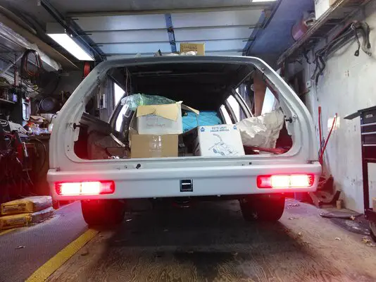
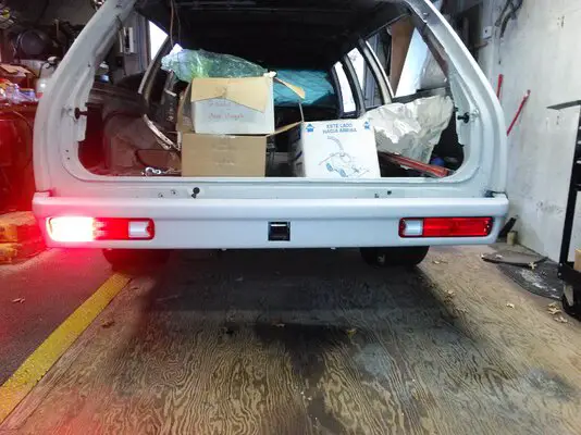
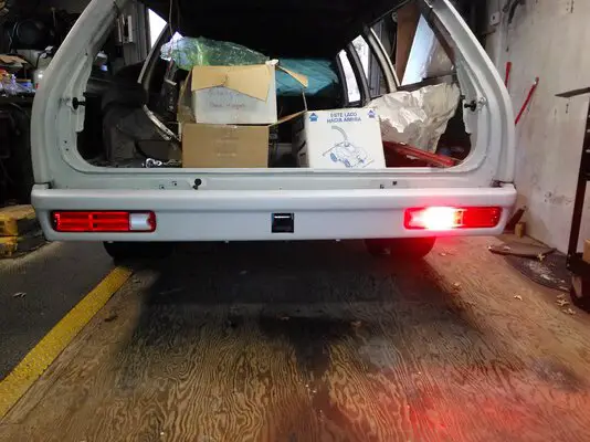
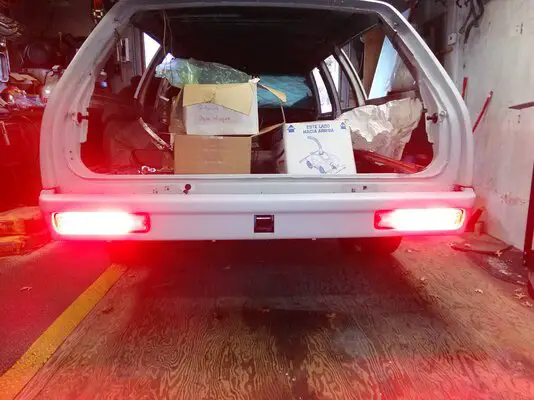
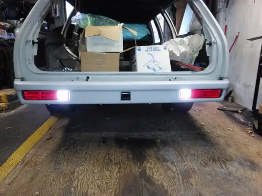
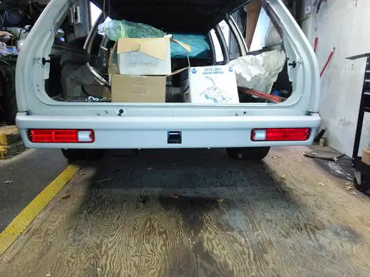
We all know that the 78-87 El Camino, and 78-83 G-body wagon, have low and difficult to see taillights. Compared to today’s vehicles with high mounted, and bright, LED taillights, these old G-body lights need some help to keep the preoccupied driver behind aware that you are stopping or turning. Spaghetti engineering recently came out with an LED taillight and back-up light conversion, Digi-tails, for these vehicles. Follow along as I install a set on my wagon.
First a few bits of technical information. There are two available conversions available, one covers the 78-81 model years, and the other the 82-87 model years. The difference is the brake lights. The 78-81 have the brake light signal running through the turn signal circuit, while the 82-87 have a dedicated brake light wire and a separate wire for left and right turn. I haven’t verified that this is absolute for every car, so it is best to check you taillight wiring before ordering a set. The schematics and detailed installation instructions are available right from the Digi-tails website.
You may need a no load digital flasher, or you may not. If you are running incandescent bulbs in every other location you may be fine with your factory flashers. If you are like me, I have LEDs in every location, except the headlights, so I ordered two no load digital flashers right from Spaghetti Engineering.
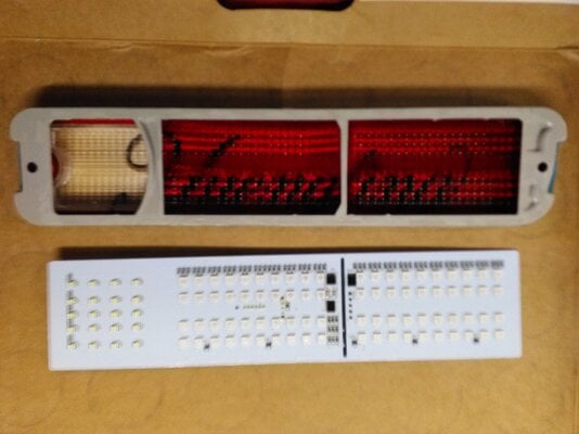
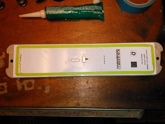
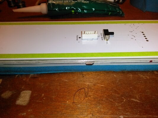
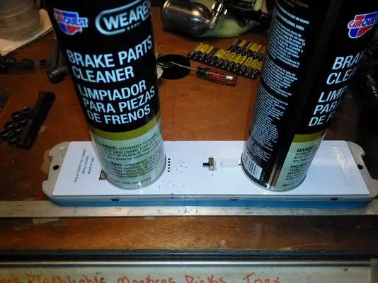
These LED boards have a total or 100 super bright LEDs. The tail lights can be configured for sequential turn and none sequential turn by the flip of the switch on the back of the board. I’ll be using the sequential function.
One other thing to note, if you have a 1978 model, the reverse lights are in a different location than the 79-87 models, so to use these LED taillights, you’ll need to acquire a set of later taillight lenses.
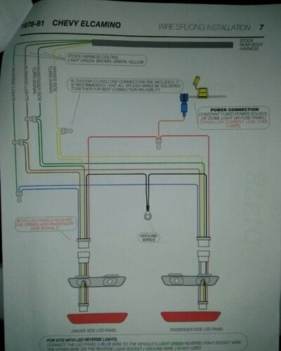
Everything is clearly labeled and neatly packaged. The instructions are clearly written with color photos for reference, and color schematics for the wiring.
The contents of the package are:
· Two LED panels
· 1 orange power wire with T-tap
· 12” pigtail harness for the left panel
· 24” pigtail harness for the right panel
· 2 12’ extension harnesses
· Silicone adhesive
· Crimp terminals
· Instructions
The included wiring instructions are straightforward and easy to follow. My vehicle has a heavily modified electrical system so using my wiring for the article won’t benefit the reader, since nothing is stock. But here is a picture of the supplied wiring diagram.
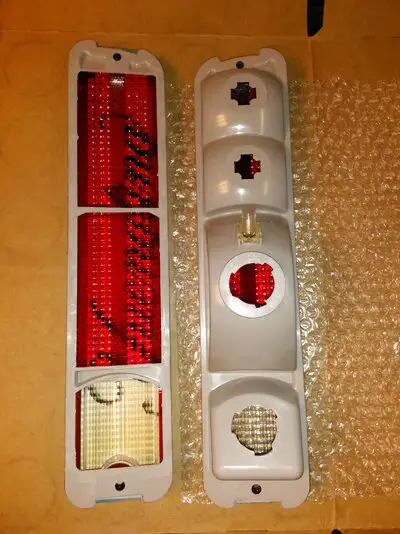
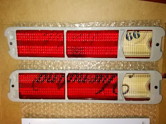
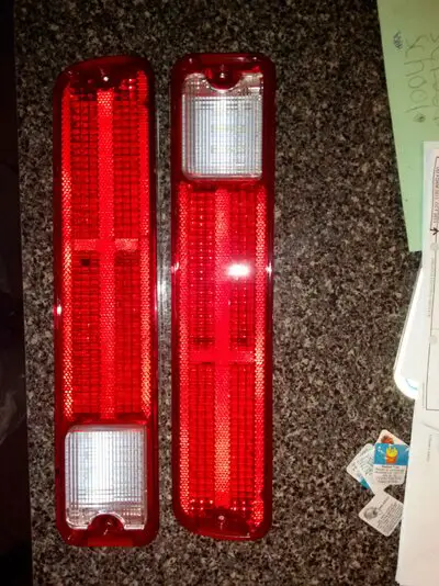
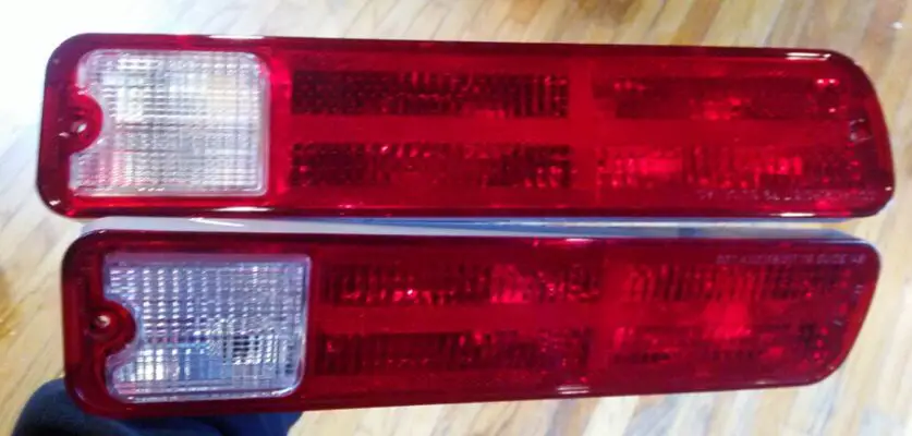
I purchased brand new 79-87 taillights from an online vender for this install. The original lenses were cloudy and the reverse lights weren’t clear anymore, but a dingy yellow, so I decided to use new lenses to get the full benefit of the brighter LEDs.
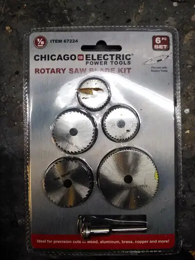
Since I will be cutting plastic, I it up the local Harbor Freight and picked up the cutting wheels for my Dremel tool.
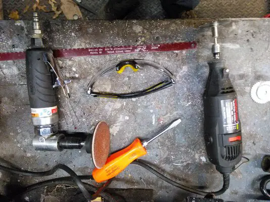
Any number of tools can be used, and I will. I have a pneumatic cut-off wheel, a pneumatic saw, hand files, drill, etc., whatever will allow me to get the cleanest cuts.
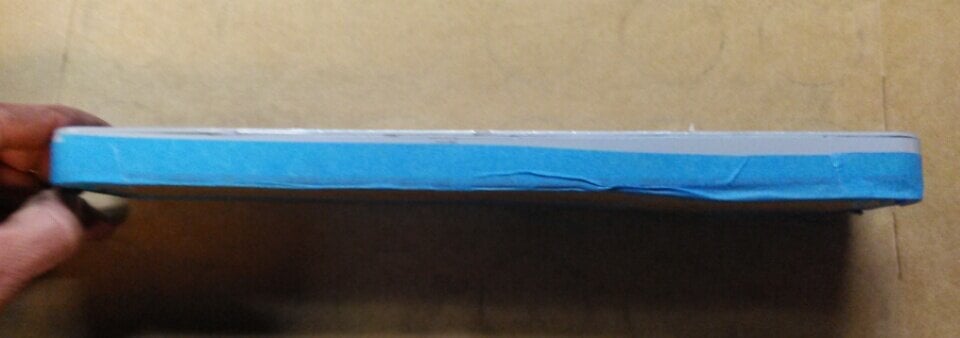
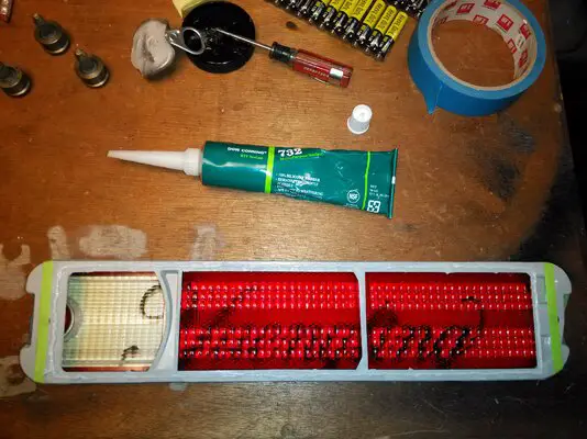
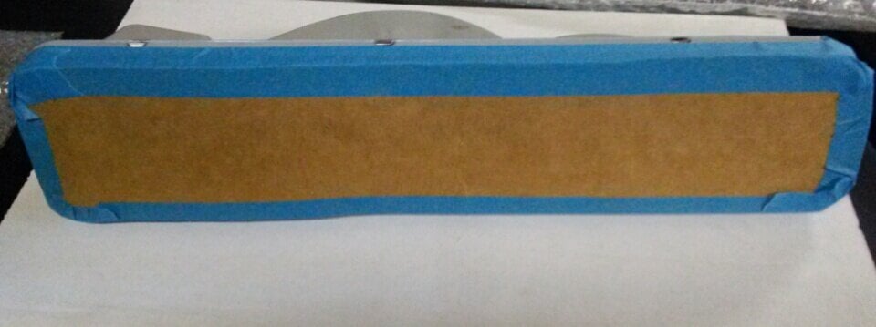
First thing I did was mask of the lens face and edge so I did not damage it, these are brand new lenses after all. I used on old beer box and some blue masking tape.
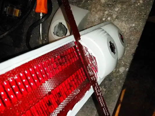
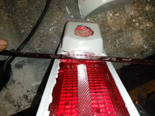
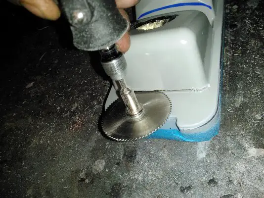
Using the instructions as a guide, I took my Dremel tool with the cutting wheel and cut off the bulb socket bubbles from the back of the lens. First thing I did was cut around the perimeter of the lens.
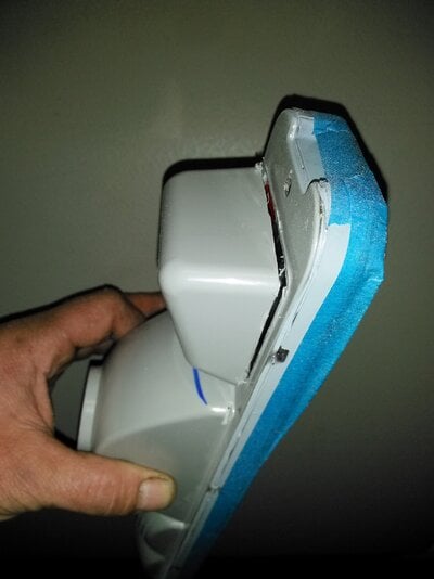
To cut out each "bubble", you need to take your cutting tool and cut in between them, I made a blue line to represent where to cut.
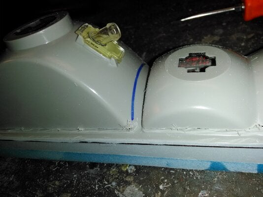
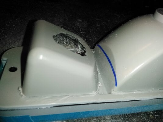
After cutting along the middle, I was able to take out the largest bubble.
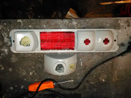
Continued.....
First a few bits of technical information. There are two available conversions available, one covers the 78-81 model years, and the other the 82-87 model years. The difference is the brake lights. The 78-81 have the brake light signal running through the turn signal circuit, while the 82-87 have a dedicated brake light wire and a separate wire for left and right turn. I haven’t verified that this is absolute for every car, so it is best to check you taillight wiring before ordering a set. The schematics and detailed installation instructions are available right from the Digi-tails website.
You may need a no load digital flasher, or you may not. If you are running incandescent bulbs in every other location you may be fine with your factory flashers. If you are like me, I have LEDs in every location, except the headlights, so I ordered two no load digital flashers right from Spaghetti Engineering.
These LED boards have a total or 100 super bright LEDs. The tail lights can be configured for sequential turn and none sequential turn by the flip of the switch on the back of the board. I’ll be using the sequential function.
One other thing to note, if you have a 1978 model, the reverse lights are in a different location than the 79-87 models, so to use these LED taillights, you’ll need to acquire a set of later taillight lenses.
Everything is clearly labeled and neatly packaged. The instructions are clearly written with color photos for reference, and color schematics for the wiring.
The contents of the package are:
· Two LED panels
· 1 orange power wire with T-tap
· 12” pigtail harness for the left panel
· 24” pigtail harness for the right panel
· 2 12’ extension harnesses
· Silicone adhesive
· Crimp terminals
· Instructions
The included wiring instructions are straightforward and easy to follow. My vehicle has a heavily modified electrical system so using my wiring for the article won’t benefit the reader, since nothing is stock. But here is a picture of the supplied wiring diagram.

I purchased brand new 79-87 taillights from an online vender for this install. The original lenses were cloudy and the reverse lights weren’t clear anymore, but a dingy yellow, so I decided to use new lenses to get the full benefit of the brighter LEDs.

Since I will be cutting plastic, I it up the local Harbor Freight and picked up the cutting wheels for my Dremel tool.

Any number of tools can be used, and I will. I have a pneumatic cut-off wheel, a pneumatic saw, hand files, drill, etc., whatever will allow me to get the cleanest cuts.

First thing I did was mask of the lens face and edge so I did not damage it, these are brand new lenses after all. I used on old beer box and some blue masking tape.

Using the instructions as a guide, I took my Dremel tool with the cutting wheel and cut off the bulb socket bubbles from the back of the lens. First thing I did was cut around the perimeter of the lens.


To cut out each "bubble", you need to take your cutting tool and cut in between them, I made a blue line to represent where to cut.


After cutting along the middle, I was able to take out the largest bubble.

Continued.....
Last edited:


 Verrrry interesting.