What Did You Do To Your G-Body Today? [2021]
- Thread starter CopperNick
- Start date
You are using an out of date browser. It may not display this or other websites correctly.
You should upgrade or use an alternative browser.
You should upgrade or use an alternative browser.
- Status
- Not open for further replies.
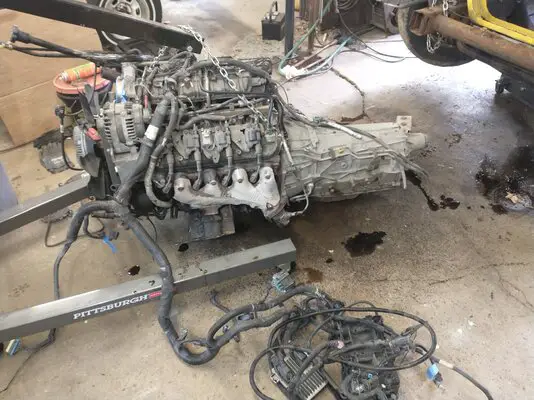
Not quite to it, but for it!
View attachment 188024
Sh!zz is about to get real!
Peel it back like a tin can!

Not to my G-Body either but sort of a harf-n-harf between about it and in the shop, not to the shop.


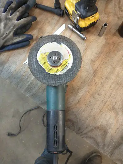
So what we have here is something i designed and fabricated to solve a clearance problem in two dimensions.
In picture three, you can clearly see the duck foot. This portion was harvested from an adaptor that was originally designed to bolt to an SBC balancer using the three pulley to balancer bolts. As originally created it had an end cap that was punched for a 1/2 drive ratchet and extension. However, when I went to test fit it, I found that it would not fit over an aftermarket balancer to crankshaft centre bolt. Stocker, maybe, but the part I used for that application came with a thicker/deeper hex head on it and there wasn't enough depth in the tool pocket to land it flush against the bottom of the pulley.
Pics One and Two are profile shots of my creation as seen in a vertical and horizontal position. To gain the needed depth to accommodate the bolt head, I decided to split the adaptor apart and add some extra body to it. SURPRISE#!! The tool was made of hardened steel. I had chucked it into my lathe and took a run at it with a carbide tipped cutter and the tool bit lasted about .100" before dulling out and refusing to cut any more. Left the adaptor chucked into position and retired to give it some more thought. Decided to scare up some more tool bits as the first one had not been exactly all that sharp to begin with and see what a fresh sharp bit would do.. Turns out, about another .100" before it too gave up the fight. All in it took three tool bits to get the width and depth needed to remove that end cap from the adaptor. The final parting was accomplished using a large socket and extension, encouraged by a plastic faced hammer to pop the end off. I did not want to try for a parting off cut because the cap could get thrown by the chuck while spinning. I like my teeth.
Back to Pic Three for just a minute because it also shows the internal tacks that I set to lock the foot onto its new body. The new body?? Well that is a 1-9/16ths" deep impact socket. Its external diameter is a great match for the diameter of the body section left behind when I split the end cap off the foot. For better weld penetration I chamfered off the hex end of the socket to get a relief into which the weld could be run. Oddly enough, even being an impact socket, it was still soft enough that a carbide tipped tool bit would work with ease.
To jig the two sections together precisely I used three short lengths of 1/2" x 1/8" angle iron and clamped them to the socket using two large gear clamps. I left enough of the angle standing proud that it would center the foot as well, tapped the angle down to get a little clearance as well as let the foot butt up tight to the face of the socket, used a third gear clamp to secure the foot and was good to go.
Apparently my Miller loves heavy metal. I set it up for 3/16th" thickness, guesstimated the feed rate and laid my tacks as like it was a production run. Pic three shows the group of six tacks, one per hex face, that I laid in. With them done, I added three more into the relief cut in the outer edge. The plan is to have the final pass done using stick weld. I could just go with the wire feed but may have to adjust the Wfps, wire feed per second, to slow it down some just to get a little more lingering time for more heat soak for a better burn in. The trade off is that too much heat could pull the hardening from the foot plate and that would ruin it.
Pic Four shows the drive end of things. The socket is a 3/4" drive and when I bought it I also scored a reducer drive adaptor, which you can see on the left. Thing here is that I don't own a 3/4 drive power bar and didn't see the logic in acquiring one just for this tool alone. So what I did was to pay a visit to my local Indie speed shop and score another pinion yoke torquing plate; that being the flat plate that bolts to the rear pinion yoke and lets you hold it in position while you preload the pinion bearing nut for drag. A whole 'nother story.
These plates come broached for two sizes of ratchet drives, 1/2 and 3/4, so what I ended up doing was to cut away the portion of the plate that had the two drive holes and discard the rest. Then I used the 3/4 reducer adaptor as a jig by fitting the segment of plate onto it and then plugging them both into the drive end of the socket. It all got held in place by using a very deep C-clamp and then I tacked that all together as well, See Pics two and Four
Yeah, the drive end looks clumsy right now. What will happen next is a test drive of the tool to see if I did my sums correctly and got the space I needed. After that, all the excess nerds and bumps will be cut away and the final passes made.
In its final form, what this creation will do is three fold. As first noted it will be used to secure the crank so that the balancer bolt can be tightened. Along with that it will be used to turn the crank during my periodic pre-oiling priming of the motor to make sure all the galleries and bearings/bushings have sufficient oil present and taking care of business so that that first fire will not cause any damage. I could just use a socket and ratchet on the balancer bolt but that has the risk of buggering the torque value applied to that bolt to set it correctly. As a bonus, I can use it to tweak the crank/cam location for my timer drop to get it as close as possible. That little exercise is still pending although I have a fresh timer built and waiting to go.
Some Fun, Huh, Bambi?????
Nick
Last edited:
The CO's will want you to put a tape on it to see if is long enough but it looks like a keeper to me.
Nick
Nick
Hey, I haven't even sat down to breakfast yet!!! Maybe a little bit, a little later. Sheesh.
Nick
Nick
I cut off the factory mounts from the Intrepid dual fans and modified the shroud to fit my new Griffen radiator and then made mounting brackets out of aluminum.
The radiator is 31" x 19" with 2 x 1.25" tubes.


The radiator is 31" x 19" with 2 x 1.25" tubes.


Last edited:
That looks nice. Aftermarket replacement fans? They look new....
- Status
- Not open for further replies.
Similar threads
- Replies
- 106
- Views
- 5K
- Replies
- 176
- Views
- 12K
- Replies
- 983
- Views
- 63K
- Replies
- 79
- Views
- 3K
GBodyForum is a participant in the Amazon Services LLC Associates Program, an affiliate advertising program designed to provide a means for sites to earn advertising fees by advertising and linking to amazon.com. Amazon, the Amazon logo, AmazonSupply, and the AmazonSupply logo are trademarks of Amazon.com, Inc. or its affiliates.


